Introduction
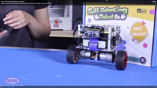
In this article, we describe the inner workings of a self-balancing, two-wheeled robot based on the Terasic DE10-Nano Kit. This small robot can balance and move using motion and balance sensors for input, and Proportional-Integral-Derivative (PID) controllers to drive the wheels. An ultrasonic sensor functions as the ears of our robot and enables the robot to avoid obstacles or chase after moving objects.
Audience
This article is for developers who’d like to learn more about the Terasic self-balancing robot, understand how it was designed, and explore some of the architectural decisions that were made. This robot uses a Cyclone™ V SoC FPGA from Intel® as the system controller and demonstrates several advantages (what we refer to as “virtues”) of using Intel® FPGAs in embedded systems. While the motivation here is not to promote FPGAs for use in robotics (although they can be an excellent choice) it does demonstrate what developers can do with FPGAs; in this case, configuring an FPGA to be a custom microcontroller tailored to specific design requirements of a self-balancing robot.
Prerequisites for developers
Before developing robotics applications on this platform, we recommend that users be familiar with FPGAs (in general) and the Terasic DE10-Nano kit. Here are some resources that can help:
- Discover the Terasic DE10-Nano kit
- Use the Quartus software to program your first FPGA device
- Use the Qsys tool to create a custom FPGA hardware design
Architecture Overview
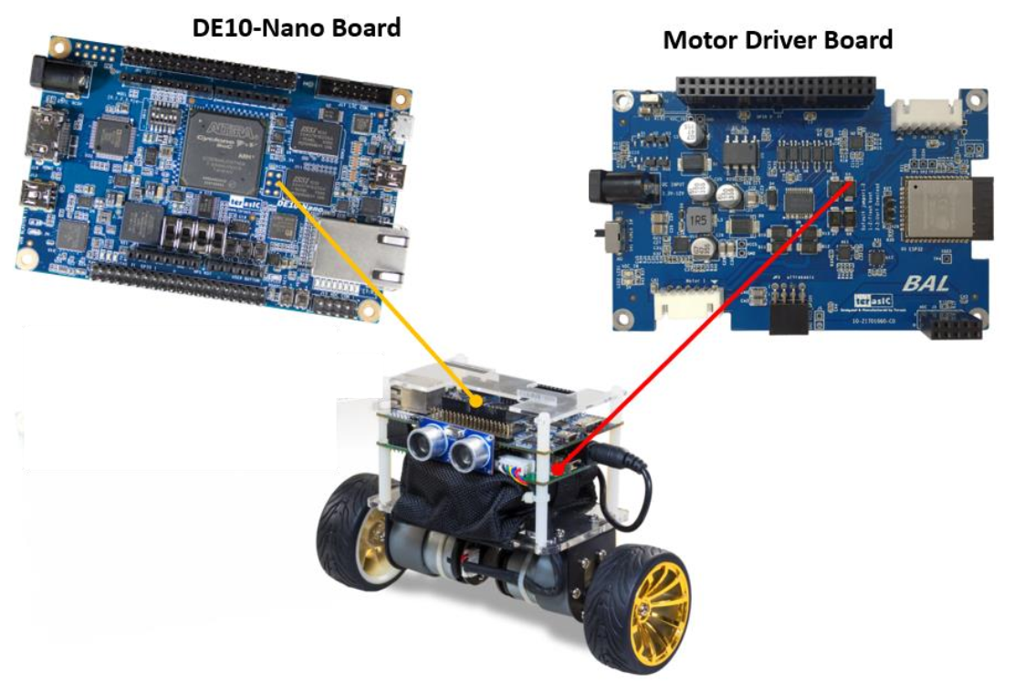
The self-balancing robot system is built using two main boards:
- Terasic DE10-Nano board
- Motor Driver board
These two boards work together to comprise the balance and control systems of our self-balancing robot.
Hardware
The DE10-Nano board is dedicated to managing the operation of the robot. To drive the wheels, the DE10-Nano board sends signals via GPIO to the Motor Driver board which then drives the motors. Sensors on the Motor Driver board provide inputs to the system which can then determine what adjustments need to be made for the robot to keep its balance and move.
Terasic DE10-Nano board
The DE10-Nano board is based on a Cyclone® V SoC FPGA from Intel® which combines a Hard Processor System (HPS), containing and ARM* CPU, a set of peripherals, and programmable logic (FPGA) on the same physical silicon die. That means there are two processor options to choose from for controlling the robot. Users can choose to execute the balance algorithm entirely with the ARM processor or implement a Nios II 32-bit embedded processor within the FPGA fabric.
Note: For the purposes of this article, we describe a design based on a Nios II embedded processor. For details on selecting between the ARM And Nios II processors, see section 3.1 Configuration Mode Switches of the Self-Balancing Get Started Guide available on the Terasic website.
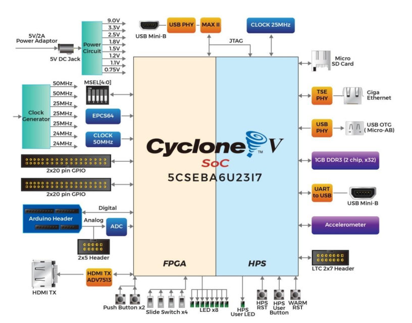
DE10-Nano board Block Diagram
ARM processor
The ARM processor, when used for robot control, gets its boots code from the SDCard plugged into the DE10-Nano board. It runs U-boot to initialize the HPS and load the FPGA image. It then boots Linux*, on top of which it runs the algorithms to control the system (i.e. balance, movement, object avoidance, etc.).
Nios® II “soft” processor
The default configuration mode uses a Nios II processor within the FPGA to control the robot. That is, we dedicate the Nios II CPU to manage the balance and movement algorithms for the robot. We have two reasons for implementing a Nios II within the FPGA. First, it demonstrates how a CPU within the FPGA can offload the ARM processor from the job of controlling the robot, freeing it for other processing tasks and ultimately boosting system performance. Second, using a Nios II processor for real-time applications can be easier for people familiar with writing bare-metal code (i.e. no OS) for a microcontroller.
Note: Here “soft” means that the Nios II processor and its peripherals (I/O) are written in a hardware description language (Verilog or VHDL)—that is, we can implement the processor architecture entirely within the programmable logic of the FPGA.
Motor Driver Board
The Motor Driver board contains sensors necessary for balance and movement, receives control signals from the FPGA to drive the robot wheels, and provides a communication interface for remote control of the robot via Bluetooth.

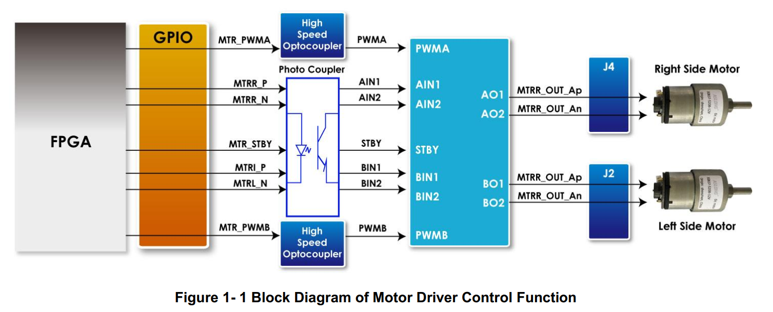
FPGA Interface to the Motor Control Board
Motors
The motors drive the wheels of the robot and are controlled by a motor driver IC (Toshiba TB6612FNG).
Sensors
Sensors on the Motor Driver board let us determine the state of the robot (e.g. balance, movement, distance from an object, etc.). The measured values from these sensors are inputs to control algorithms implemented as proportional-integral-derivative (PID) control loops. Interfaces which communicate with the sensors on the Motor Driver board are implemented as soft IP cores (i.e. functions implemented within the FPGA fabric). The orange blocks in the figure above represent these soft IP cores.
Note: With this design, we demonstrate one FPGA “virtue” which is the ability to adapt the set of I/O functions to match system requirements. If we’d like to include more sensors for additional functionality, we can simply add the appropriate interface IP core in the FPGA and assign its I/O signals to the appropriate FPGA pins.
MPU-6500 (accelerometer and gyroscope)
The MPU-6500 is a single chip that integrates a 3-axis accelerometer, a 3-axis gyroscope, and a digital motion processor in a single device. Data from this sensor is used to determine the tilt angle of the robot.
Note: While the DE10-Nano board has a built in 3-axis accelerometer (ADXL345), it is not used here for the Self-Balancing Robot application. Instead, the Motor Driver board uses a MPU-6500 to determine the tilt angle of the robot. This sensor provides a more accurate measurement of the tilt angle because of the additional data that comes from the gyroscope.
Ultrasonic sensor
An ultrasonic sensor measures the distance between the robot and an object in front of it. We use data from this sensor to enable the robot to avoid obstacles, or to follow an object.
Hall Effect sensor
Hall Effect sensors are positioned on the motors to determine the direction and speed of the wheels.
| Sensors | Purpose | What it Measures | Location |
|---|---|---|---|
| MPU-6500 (accelerometer + gyroscope) | Provides input data to maintain upright position (when stationary or in motion) | Tilt angle, θ | Motor Driver board |
| Ultrasonic sensor | Measures distance from an object to avoid obstacles or follow objects | Distance | Motor Driver board |
| Hall effect sensors | Provides input data used to control the motors | Rotational speed and direction of the wheels | Attached to the DC motors |
Bluetooth Module
The Bluetooth module enables users to remote control the robot by a smartphone app. Users can download the smartphone app from the Terasic* website here.
Software
By default, the balance and movement algorithms run on the Nios II processor implemented within the FPGA.
Architectural Decisions & Implementation
Robotics applications often use standard, off-the-shelf, microcontrollers. But robotics applications can also benefit from a “custom” microcontroller (i.e., processor plus a peripheral set tailored to the specific robotic requirements). Sometimes off-the-shelf microcontrollers don’t have the specific set of peripherals needed, requiring additional devices to fill the gaps. Or, a more full-featured microcontroller is needed, which adds to system cost.
Choosing to Implement a Nios II “Soft” Processor
In the case of the self-balancing robot, we don’t replace the main processor (ARM) with the soft processor (Nios II) but instead make the Nios II CPU responsible for controlling the robot while the ARM processor is free to handle other system tasks for which it is more suited (e.g. running Linux, managing a file system, providing a web server interface, etc.).
We demonstrate three key advantages (virtues) to using a soft processor (Nios II) within the FPGA and by using the FPGA in general:
- I/O Expansion: With our robot, we expand I/O capabilities by choosing the exact type and number of peripherals needed to control the robot. We can also tailor the I/O to our specific application by defining custom peripherals (UART, PWM, CAN bus, etc.).
- Boost Performance: When we offload the ARM processor by configuring the FPGA to be responsible for the balance and control systems of the robot, the ARM processor is now free to run other tasks boosting system performance or adding new capabilities.
- Adapt to change: Inevitably, we will want to add new functions to the robot. For example, we can add a camera module to give the robot vision, letting it locate, track, and follow objects. By using an FPGA we can modify our hardware design, adding interfaces to support the camera board.
Controlling the Robot
The General Purpose I/O (GPIO) pins on the Cyclone V SoC FPGA don’t provide enough current to drive the motors directly (they provide milliamps of current, not amps). Instead, they are responsible for sending the control signals to the Motor Driver board which produces enough power to drive the motors.
The role of the Motor Driver Board
The Motor Driver board receives control signals from the FPGA and uses them to control the output of a motor driver IC (a Toshiba TB6612FNG) to drive the DC motors of our two-wheeled robot.
Basic Operation: Balance and Control Systems
Balance and Movement
Since the robot only has two wheels, a balance system is needed to make sure the robot always stays upright and doesn’t fall over. Sensors measure the robot tilt angle which the Nios II processor uses to calculate how much, and in which direction, to drive the wheels.
We also want the robot to move, not just stand in one place, so a separate control system is needed to work in conjunction with the balance system move the robot forward, backward, and to turn.
How Balancing Works
To understand what’s required for balancing our robot, we must appreciate the physics of an inverted pendulum—a pendulum with its center of mass above its pivot point. The self-balancing robot is like an inverted (or upside down) pendulum. That means most of the robot’s weight, or its center of mass, is located above its pivot point (in this case, somewhere near wheels).
What results from this setup is an inherently unstable robot that must be actively balanced to maintain its upright position. That requires us to implement a feedback and correction mechanism to monitor our robot’s state (such as measurements of its speed and tilt angle) and then adjust the instant something happens to keep it from taking a tumble or crashing into a wall. Here, the balance system acts as the feedback (sensor data that measures the robot’s state) and the control system makes corrections by sending commands to the motors (to adjust the speed and direction of the wheels).
What we do to counteract a fall
The action we take to counteract a fall is to drive the motors in the direction of the fall—our goal being to maintain the robot’s center of mass above its pivot point. This action takes a cue from human behavior—to avoid a fall, you would take a step in the direction of your fall (whether that’s forward or backward).
Closed-loop Control System
Using PID controllers, we establish a system of feedback and correction to allow the robot to continuously adjust itself. The PID controllers that make up the balance and control systems (our main algorithm) read sensor data (feedback) and determine desired output values (for example, desired angle or turn). They first calculate and then sum the proportional (P), integral (I) and derivative (D) terms (depending on the variation of PID controller). The result is then sent to the motors (correction). For our robot, Proportional Integral (PI) and Proportion Derivation (PD) controllers (variations of a PID controller) are used to generate the desired system response.
Note: Interfaces to the sensors are implemented as soft IP within the FPGA. When using an FPGA, adding more sensors is relatively easy as you can simply reconfigure the FPGA to include the interfaces for the additional functionality (sensors or additional daughter cards) you’d like to your platform.
The main algorithm functions are Balance, Velocity, and Turn.
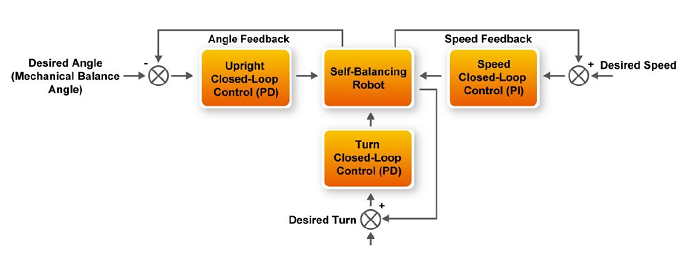
Balance & Movement Control System
Balance
The balance function is implemented as a Proportional / Derivative (PD) controller and is used for vertical control (helping our robot to maintain an upright position). We use the data from the MPU-6500 accelerometer and gyroscope as input to determine the tilt angle of the robot. The processed result is then sent to the motors to make corrections to keep our robot standing tall.
Accelerometer plus gyroscope: how we measure tilt angle
Data from the gyroscope and accelerometer are combined to measure the tilt angle, θ, of the robot. The resulting data is shown in blue on the chart below. As you can see, there is wide variability which can make the robot difficult to balance. A Kalman filter is applied to the data to reduce the variability and provide a more accurate measurement of the tilt angle, ultimately making the robot balance easier to control.
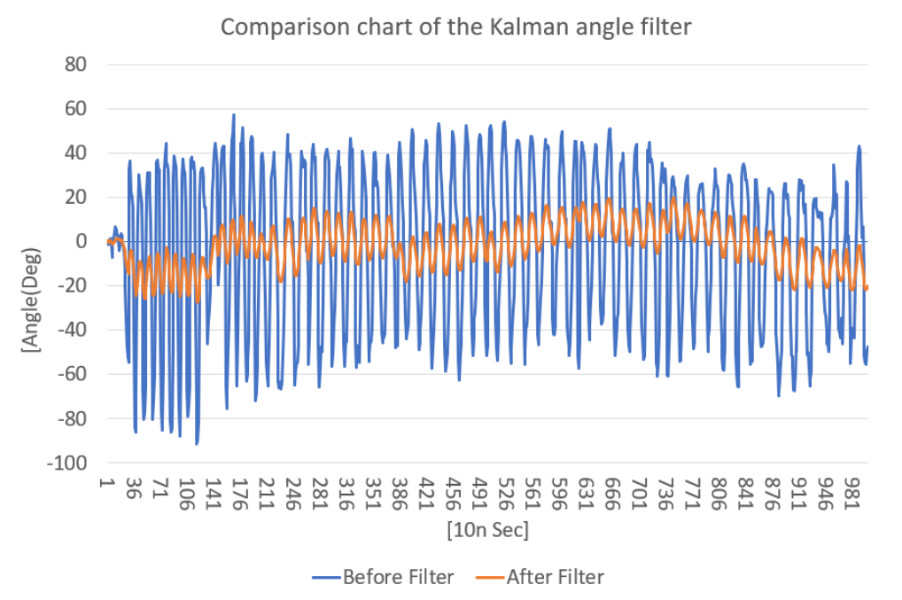
Accelerometer Plus Gyroscope Data
Velocity
The velocity control function is implemented as a Proportional / Integral (PI) controller based on input from the Hall effect sensors located near each motor shaft. When the motor rotates, a magnetic rotor attached to the shaft also turns. Magnets in the rotor pass by the Hall effect sensors causing them to generate pulses proportional to the rotational speed of the shaft.

When the magnetic rotor turns, one sensor will generate a pulse first, followed by a pulse from the second sensor. We can determine the motor rotation direction based on the phase differential between the two sensor outputs. We can also calculate the motor speed based on counting pulses over a fixed period. The faster the motor rotates the more pulses are generated.

Turn
The turn control function is implemented as a PD controller using input data from both Hall effect sensors (speed and direction) and the gyroscope to control the robot’s turn. As with the balance function, sensor data from the motor control board is processed by the Nios II CPU in the FPGA. The motor control output (PWM) then goes to the motor control board to drive the DC motors to make necessary adjustments.
Ultrasonic sensor: how we measure distance
The ultrasonic sensor functions as the ears of our robot (yes, ears and not eyes!) and enables us to measure distance. Based on the physics of reflected waves, these sensors work by emitting ultrasonic sound waves and listening for an echo. When a sound wave is reflected, we know that there is an object in front of the robot. And the time it takes for the sensor to transmit and then receive that sound wave is used to determine the distance between our robot and an object. Unlike proximity sensors (which use reflected electromagnetic waves, such as infrared, to measure distance), the ultrasonic sensor is reliable in dark environments (such as a dimly lit room).
Note: Ultrasonic denotes frequencies above 20,000 hertz (the upper audible limit for human ears meaning that ultrasonic sound waves are imperceptible to humans). You won’t hear the robot as it emits ultrasonic sound waves and listens for an echo.
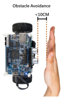
There are two operating modes for the robot based on data from the ultrasonic sensor. Users can choose to avoid obstacles, or follow moving objects. See the Terasic Self-Balancing Robot Get Started Guide for more information on how to select these modes of operation.
Obstacle avoidance
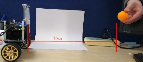
For objects that are within a distance of 10 cm from the robot, our robot will automatically avoid the object by stopping before impact.
Object following
For objects that are a distance between 10-20 cm and moving (but maintaining a distance within the specified range), the robot will follow the object.
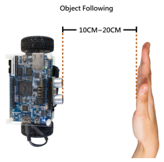
Note: For the object following mode, the robot is not controlled by the smartphone app or the IR remote control.
Bluetooth module: how we communicate with the robot
Users can download a smartphone app to remote control the robot (via Bluetooth).
Expansion Possibilities
As we mentioned before, using an FPGA makes it easy to add functionality to your system. We’ve highlighted the advantage of I/O expansion (adding interfaces in the form of soft IP blocks, for our sensors to communicate with the FPGA) as demonstrated by the robot design. Because the FPGA is reconfigurable, you can continue to customize the peripheral set according to new or changing requirements. One interesting example is adding a camera to give the robot “sight”.
Add a Camera Card
Terasic provides a low-cost, 8 mega pixel camera board which plugs directly onto one of the DE10-Nano expansion headers. A design is available for free download which allows the robot to track and follow objects based on color. In this case, an orange ping pong ball is used as the object to track. Image processing hardware within the FPGA design identifies the object based on color and provides feedback to the motor control system to follow the ball.
Learn more about adding a camera board to the robot at Digi-key* Maker.io*
Resources
Self-Balancing Robot Documentation
- DE10-Nano board schematics
- Motor Driver Board schematics
- Get Started Guide
- Quick Start Guide
- Hardware Manual
- User Guide
Useful Links
- Unboxing video
- Maker.io: Adding the camera board, Remote controller
- Intel Developer Zone: DE-10 Nano Kit
- Intel® FPGA and Intel® SoC FPGA
Where to Buy