1 Introduction
OpenStack* Enhanced Platform Awareness (EPA) contributions from Intel and others enable fine-grained matching of workload requirements to platform capabilities. EPA features provide OpenStack with an improved understanding of the underlying platform hardware (HW), which allows it accurately assign the workload to the best HW resource.
This paper explains the OpenStack EPA features listed in the table in section 1.3. Each feature is covered in isolation, with a brief description, configuration steps to enable the feature, and a short discussion of its benefits.
1.1 Audience and purpose
This document is intended to help understand the performance gains for each EPA feature in isolation. Each section has detailed information on how to configure a system to utilize the EPA feature in question.
This document focuses on EPA features available in the Newton* release. The precursor to this document can be found here.
1.2 EPA Features Covered
| Feature Name | First OpenStack* Release | Description | Benefit | Performance Data |
|---|---|---|---|---|
| Host CPU feature request | Icehouse* | Expose host CPU features to OpenStack managed guests | Guest can directly use CPU features instead of emulated CPU features | ~20% to ~40% improvement in guest computation |
| PCI passthrough | Havana* |
Provide direct access to a physical or virtual PCI device | Avoid the latencies introduced by hypervisor and virtual switching layers | ~8% improvement in network throughput |
| HugePages* support |
Kilo* |
Use memory pages larger than the standard size | Fewer memory translations requiring fewer cycles | ~10% to ~20% improvement in memory access speed |
| NUMA awareness | Juno* |
Ensures virtual CPUs (vCPU)s executing processes and the memory used by these processes are on the same NUMA node |
Ensures all memory accesses are local to the node and thus do not consume the limited cross-node memory bandwidth, adding latency to memory accesses | ~10% improvement in guest processing |
| IO based NUMA scheduling | Kilo* |
Creates an affinity that associates a VM with the same NUMA nodes as the PCI device passed into the VM | Delivers optimal performance when assigning PCI device to a guest | ~25% improvement in network throughput for smaller packets |
| CPU pinning | Kilo* | Supports the pinning of VMs to physical processors | Avoids scheduling mechanism moving the guest virtual CPUs to other host physical CPU cores, improving performance and determinism | ~10 % to ~20% improvement in guest processing |
| CPU threading policies | Mitaka* |
Provides control over how guests can use the host hyper thread siblings | More fine-grained deployment of guests on HT-enabled systems | Up to ~50% improvement in guest processing |
| OVS-DPDK, neutron | Liberty* |
An industry standard virtual switch accelerated by DPDK | Accelerated virtual switching | ~900% throughput improvement |
2 Test Configuration
Following is an overview of the environment that was used for testing the EPA features covered in this document.
2.1 Deployment
Several OpenStack deployment tools are available. Devstack which is basically a script used to configure and deploy each OpenStack service, was used for to demonstrate EPA features in this document. Devstack uses a single configuration file to determine the functionality of each node in your OpenStack cluster. Devstack modifies each OpenStack service configuration file to reflect the user's requirements defined in the configuration file.
To avoid dependency on a particular OpenStack deployment tool, the respective OpenStack configuration file that was modified for the respective service will be mentioned.
2.2 Topology
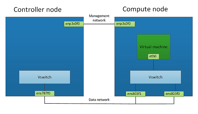
Figure 1: Network topology
2.3 Hardware
| Item | Description | Notes |
|---|---|---|
| Platform | Intel® Server System R1000WT Family | |
| Form factor | 1U Rack | |
| Processor(s) | Intel® Xeon® CPU E5-2699 v4 @ 2.20GHz | 55MB Cache with Hyper-threading enabled |
| Cores | 44 physical cores/CPU | 44 hyper-threaded cores per CPU for 88 total cores |
| Memory | 132G RAM | DDR4 2133 |
| NIC’s | 2 * Intel® Ethernet Controller 10 Gigabit 82599 | |
| BIOS | SE5C610.86B.01.01.0019.101220160604 | Intel® Virtualization Technology (Intel® VT) for Directed I/O (Intel® VT-d) Hyper-Threading enabled |
2.4 Software
| Item | Description | Notes |
|---|---|---|
| Host OS | Ubuntu 16.04.1 LTS | 4.2.0 Kernel |
| Hypervisor | Libvirt-3.1/Qemu-2.5.0 | |
| Orchestration | OpenStack (Newton release) | |
| Virtual switch | OpenvSwitch 2.5.0 | |
| Data plane development kit | DPDK 16.07 | |
| Guest OS | Ubuntu 16.04.1 LTS | 4.2.0 Kernel |
2.5 Traffic generator
An Ixia XG-12 traffic generator was used to generate the networking workload for some of the tests described in this document. To simulate a worst-case scenario from a networking perspective, 64-byte packets are used.
3 Host CPU Feature Request
This feature allows the user to expose a specific host CPU instruction set to a guest. Instead of the hypervisor emulating the CPU instruction set, the guest can directly access the host's CPU feature. While there are many host CPU features available, the Intel® Advanced Encryption Standard New Instructions (Intel® AES-NI) instruction set is used in this example.
One sample use case would be a security application requiring a high level of cryptographic performance. This could be instrumented to leverage specific instructions such as Intel® AES-NI.
The following steps detail how to configure the host CPU feature request for this use case.
3.1 Configure the compute node
3.1.1 System configuration
Before a specific CPU feature is requested, the availability of the CPU instruction set should be checked using the cpuid instruction.
3.1.2 Configure libvirt driver
The Nova* libvirt driver takes its configuration information from a section in the main Nova file /etc/nova/nova.conf. This allows for customization of certain Nova libvirt driver functionality.
For example:
[libvirt]
...
cpu_mode = host-model
virt_type = kvm
The cpu_mode option in /etc/nova/nova.conf can take one of the following values: none, host-passthrough, host-model, and custom.
host-model
Libvirt identifies the CPU model in the /usr/share/libvirt/cpu_map.xml file that most closely matches the host, and requests additional CPU flags to complete the match. This configuration provides the maximum functionality and performance, and maintains good reliability and compatibility if the guest is migrated to another host with slightly different host CPUs.
host-passthrough
Libvirt tells KVM to pass through the host CPU with no modifications. The difference between host-passthrough and host-model is that, instead of just matching feature flags, every last detail of the host CPU is matched. This gives the best performance, and can be important to some apps that check low-level CPU details, but it comes at a cost with respect to migration. The guest can only be migrated to a matching host CPU.
custom
You can explicitly specify one of the supported named models using the cpu_model configuration option.
3.2 Configure the Controller node
3.2.1 Enable the compute capabilities filter in Nova*
The Nova scheduler is responsible for deciding which compute node can satisfy the requirements of your guest. It does this using a set of filters; to enable this feature, simply add the compute capability filter.
During the scheduling phase, the ComputeCapabilitiesFilter in Nova compares the CPU features requested by the guest with the compute node CPU capabilities. This ensures that the guest is scheduled on a compute node that satisfies the guest’s PCI device request.
Nova filters are configured in /etc/nova/nova.conf
scheduler_default_filters = ...,ComputeCapabilitiesFilter,...
3.2.2 Create a Nova flavor that requests the ntel® Advanced Encryption Standard New Instructions (Intel® AES-NI) for a VM
openstack flavor set <FLAVOR> --property hw:capabilities:cpu_info:features=aes <GUEST>
3.2.3 Boot guest with modified flavor
openstack server create --image <IMAGE> --flavor <FLAVOR> <GUEST>
3.2.4 Performance benefit
This feature gives the guest direct access to a host CPU feature instead of the guest using an emulated CPU feature. This feature can deliver a double digit performance improvement, depending on the size of data buffer being used.
To demonstrate the benefit of this feature, a crypto workload (openssl speed -evp aes256) is executed on guest A that has not requested a host CPU feature, while guest B has requested the host Intel AES-NI CPU feature. Guest A will use an emulated CPU feature, while guest B will use the host's CPU feature.
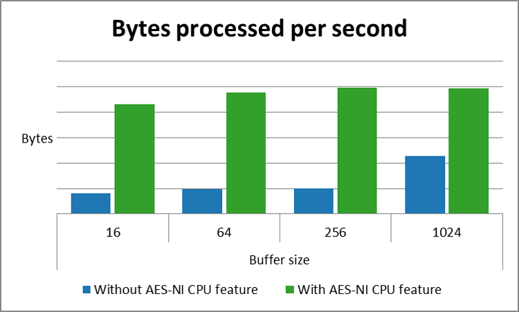
Figure 2: CPU feature request comparison
4 Sharing Host PCI Device with a Guest
In most cases the guest will require some form of network connectivity. To do this, OpenStack needs to create and configure a network interface card (NIC) for guest use. There are several methods of doing this. The one you choose depends on your cloud requirements. The table below highlights each option and their respective pros and cons.
| NIC Emulation | PCI Passthrough (PF) | SRIOV (VF) | |
|---|---|---|---|
| Overview | Hypervisor fully emulates the PCI device | The full PCI device is allocated to the guest. | A PCI device VF is allocated to the guest |
| Guest sharing | Yes | No | Yes |
| Guest IO performance | Slow | Fast | Fast |
Device emulation is performed by the hypervisor, which has an obvious overhead. This overhead is worthwhile as long as the device needs to be shared by multiple guest operating systems. If sharing is not necessary there are more efficient methods for sharing devices.
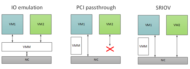
Figure 3: Host to guest communication methods
The PCI passthrough feature in OpenStack gives the guest full access and control of a physical PCI device. This mechanism can be used on any kind of PCI device, NIC, graphics processing unit (GPU), HW crypto accelerator (QAT), or any other device that can be attached to a PCI bus.
An example use case for this feature would be to pass a PCI network interface to a guest, avoiding the latencies introduced by hypervisor and virtual switching layers. Instead, the guest will use the PCI device directly.
When a full PCI device is assigned to a guest, the hypervisor detaches the PCI device from the host OS and assigns it to the guest, which means the PCI device is no longer available to the host OS. A downside of PCI passthrough is that the full physical device is assigned to only one guest and cannot be shared, and guest migration is not currently supported.
4.1 Configure the compute node
4.1.1 System configuration
Enable VT-d in BIOS.
Add “intel_iommu=on” to kernel boot line to enable the kernel.
Edit this file: /etc/default/grub
GRUB_CMDLINE_LINUX="intel_iommu=on"
sudo update-grub
sudo reboot
To verify VT-d/IOMMU is enabled on your system:
sudo dmesg | grep IOMMU
[    0.000000] DMAR: IOMMU enabled
[    0.133339] DMAR-IR: IOAPIC id 10 under DRHD base  0xfbffc000 IOMMU 0
[    0.133340] DMAR-IR: IOAPIC id 8 under DRHD base  0xc7ffc000 IOMMU 1
[    0.133341] DMAR-IR: IOAPIC id 9 under DRHD base  0xc7ffc000 IOMMU 1
4.1.2 Configure your PCI allowlist
OpenStack uses a PCI allowlist to define which PCI devices are available to guests. There are several ways to define your PCI allowlist; here is one method.
The Nova PCI allowlist is configured in: /etc/nova/nova.conf
[default]
pci_passthrough_whitelist={"address":"0000:02:00.1","vendor_id":"8086","physical_network":"default"}
4.1.3 Configure the PCI alias
Following the Newton release, you also need to configure the PCI alias on the compute node. This is to enable resizing a guest that has been allocated a PCI device.
Get the vendor and product ID of the PCI device:
sudo ethtool -i ens513f1 | grep bus-info
bus-info: 0000:02:00.1

sudo lspci -n | grep 02:00.1
02:00.1 0200: 8086:10fb (rev 01)
Nova PCI alias tags are configured in: /etc/nova/nova.conf
[default]
pci_alias = {"vendor_id":"8086","product_id":"10fb","device_type":"type-PF", "name":"nic" }
NOTE: To pass through a complete PCI device, you need to explicitly request a physical function in the pci_alias by setting the device_type = type-PF.
4.2 Configure the Controller Node
Nova scheduler is responsible for deciding which compute node can satisfy the requirements of your guest. It does this using a set of filters; to enable this feature add the PCI passthrough filter.
4.2.1 Enable the PCI passthrough filter in Nova
During the scheduling phase, the Nova PciPassthroughFilter filters compute nodes based on PCI devices they expose to the guest. This ensures that the guest is scheduled on a compute node that satisfies the guest’s PCI device request.
Nova filters are configured in: /etc/nova/nova.conf
scheduler_default_filters = ...,ComputeFilter,PciPassthroughFilter,...
NOTE: If you make changes to the nova.conf file on a running system, you will need to restart the Nova scheduler and Nova compute services.
4.2.2 Configure your PCI device alias
To make the requesting of a PCI device easier you can assign an alias to the PCI device. Define the PCI device information with an alias tag and then reference the alias tag in the Nova flavor.
Nova PCI alias tags are configured in: /etc/nova/nova.conf
Use the PCI device vendor and product ID obtained from step 4.1.3:
[default]
pci_alias = {"vendor_id":"8086","product_id":"10fb","device_type":"type-PF", "name":"nic" }
NOTE: To pass through a complete PCI device you must explicitly request a physical function in the pci_alias by setting the device_type = type-PF.
Modify Nova flavor
If you request a PCI passthrough for the guest, you also need to define a non-uniform memory access (NUMA) topology for the guest.
openstack flavor set <FLAVOR> --property  "pci_passthrough:alias"="nic:1"
openstack flavor set <FLAVOR> --property  hw:numa_nodes=1
openstack flavor set <FLAVOR> --property  hw:numa_cpus.0=0
openstack flavor set <FLAVOR> --property  hw:numa_mem.0=2048
Here, an existing flavor is modified to define a guest with a single NUMA node, one vCPU and 2G of RAM, and a single PCI physical device. You can create a new flavor if you need one.
4.3 Boot guest with modified flavor
openstack server create --image <IMAGE> --flavor <FLAVOR> <GUEST>
4.4 Performance benefit
This feature allows a PCI device to be directly attached to the guest, removing the overhead of the hypervisor and virtual switching layers, delivering a single digit gain in throughput.
To demonstrate the benefit of this feature, the conventional path a packet takes via the hypervisor and virtual switch is compared with the optimal path, bypassing the hypervisor and virtual switch layers.
Using these test scenarios, iperf3 is used to measure the throughput, and ping (ICMP) to measure the latencies for each scenario.

Figure 4: Guest PCI device throughput

Figure 5: Guest PCI device latency
4.5 PCI virtual function passthrough
The preceding section covered the passing of a physical PCI device to the guest. This section covers passing a virtual function to the guest.
Single root input output virtualization (SR-IOV) is a specification that allows a single PCI device to appear as multiple PCI devices. SR-IOV can virtualize a single PCIe Ethernet controller (NIC) to appear as multiple Ethernet controllers. You can directly assign each virtual NIC to a virtual machine (VM), bypassing the hypervisor and virtual switch layer. As a result, users are able to achieve low latency and near-line rate speeds. Of course, the total bandwidth of the physical PCI device will be shared between all allocated virtual functions.
The physical PCI device is referred to as the physical function (PF) and a virtual PCI device is referred to as a virtual function (VF). Virtual functions are lightweight functions that lack configuration resources.
The major benefit of this feature is that it makes it possible to run a large number of virtual machines per PCI device, which reduces the need for hardware and the resultant costs of space and power required by hardware devices.
4.6 Configure the Compute node
4.6.1 System configuration
Enable VT-d in BIOS.
Add “intel_iommu=on” to kernel boot line to enable the kernel. Edit this file: /etc/default/grub
GRUB_CMDLINE_LINUX="intel_iommu=on"
sudo update-grub
sudo reboot
To verify that VT-d/IOMMU is enabled on your system, execute the following command:
sudo dmesg | grep IOMMU
[    0.000000] DMAR: IOMMU enabled
[    0.133339] DMAR-IR: IOAPIC id 10 under DRHD base  0xfbffc000 IOMMU 0
[    0.133340] DMAR-IR: IOAPIC id 8 under DRHD base  0xc7ffc000 IOMMU 1
[    0.133341] DMAR-IR: IOAPIC id 9 under DRHD base  0xc7ffc000 IOMMU 1
4.6.2 Enable SR-IOV on a PCI device
There are several ways to enable a SR-IOV on a PCI device. Here is a method to enable a single virtual function on a PCI Ethernet controller (ens803f1):
sudo su -c "echo 1 > /sys/class/net/ens803f1/device/sriov_numvfs"
4.6.3 Configure your PCI allowlist
OpenStack uses a PCI allowlist to define which PCI devices are available to guests. There are several ways to define your PCI allowlist; here is one method.
The Nova PCI allowlist is configured in: /etc/nova/nova.conf
[default]
pci_passthrough_whitelist= {"address":"0000:02:10.1","vendor_id":"8086","physical_network":"default"}
4.6.4 Configure your PCI device alias
See section 3.2.2 for PCI device alias configuration.
NOTE: To pass through a virtual PCI device you just need to add the vendor and product ID for the device. If you use the PF PCI address, all associated VFs will be exposed to Nova.
4.7 Configure the controller node
4.7.1 Enable the PCI passthrough filter in Nova
Follow the steps described in section 4.2.1.
4.7.2 Configure your PCI device alias
To make the requesting of a PCI device easier you can assign an alias to the PCI device, define the PCI device information with an alias tag, and then reference the alias tag in the Nova flavor.
Nova PCI alias tags are configured in: /etc/nova/nova.conf
Use the PCI info obtained in step 4.1.3:
[default]
pci_alias = {"vendor_id":”8086","product_id":"10ed", "name":"nic" }
NOTE: To pass through a virtual PCI device (VF) you just need to add the vendor and product id of the VF.
Modify Nova flavor
If you request PCI passthrough for the guest, you also need to define a NUMA topology for the guest.
openstack flavor set <FLAVOR> --property  "pci_passthrough:alias"="nic:1"
openstack flavor set <FLAVOR> --property  hw:numa_nodes=1
openstack flavor set <FLAVOR> --property  hw:numa_cpus.0=0
openstack flavor set <FLAVOR> --property  hw:numa_mem.0=2048
Here, an existing flavor is modified to define a guest with a single NUMA node, one vCPU and 2G of RAM, and a single PCI physical device. You can create a new flavor if you need to.
4.7.3 Boot guest with modified flavor
openstack server create -–image <IMAGE> --flavor <FLAVOR> <GUEST-NAME>
5 Hugepage Support
5.1 Description
When a process uses memory the CPU marks the RAM as used by the process. This memory is divided into chunks of 4KB, or pages. The CPU and operating system must remember where in memory these pages are and to which process they belong. When processes begin to use large amounts of memory, lookups can take a lot of time; this is where hugepages come in. Depending on the processor two different huge page sizes can be used on x86_64 architecture, 2MB or 1GB. Using these larger page sizes makes lookups much quicker.
To show the value of hugepages in OpenStack, the “sysbench” benchmark suite is used along with two VMs; one with 2MB hugepages and one with regular 4KB pages.
5.2 Configuration
5.2.1 Compute host
First, enable hugepages on the compute host
sudo mkdir -p /mnt/huge
sudo mount -t hugetlbfs nodev /mnt/huge
sudo echo 8192 > \ /sys/devices/system/node/node0/hugepages/hugepages-2048kB/nr_hugepages
If 1GB hugepages are needed it is necessary to configure this at boot time through the GRUB command line. It is also possible to set 2MB hugepages at this stage.
GRUB_CMDLINE_LINUX="default_hugepagesz=1G hugepagesz=1G hugepages=8”
Enable hugepages to work with KVM/QEMU and libvirt. First, edit the line in the qemu-kvm file:
				vi /etc/default/qemu-kvm

				#Edit the line to match the line below
				KVM_HUGEPAGES=1
Now, tell libvirt where the hugepage table is mounted, and edit the security driver for libvirt. Add the hugetlbfs mount point to the cgroup_device_acl list:
vi /etc/libvirt/qemu.conf

security_driver = "none"
hugetlbfs_mount = "/mnt/huge"

cgroup_device_acl = [
"/dev/null", "/dev/full", "/dev/zero",
"/dev/random", "/dev/urandom",
"/dev/ptmx", "/dev/kvm", "/dev/kqemu",
"/dev/rtc", "/dev/hpet","/dev/net/tun",
"/dev/vfio/vfio","/mnt/huge"
]
Now restart libvirt-bin and the Nova compute service:
sudo service libvirt-bin restart
sudo service nova-compute restart
5.2.2 Test
Create a flavor that utilizes hugepages. For this benchmarking work, 2MB pages are utilized.
On the Controller node, run:
openstack flavor create hugepage_flavor --ram 4096 --disk 100 --vcpus 4
openstack flavor set hugepage_flavor --property hw:mem_page_size=2MB
To test hugepages, a VM running with regular 4KB pages and one using 2MB pages are needed. First, create the 2MB hugepage VM:
On the Controller node, run:
openstack server create --image ubu160410G --flavor hugepages --nic \ net-id=e203cb1e-988f-4bb5-bbd1-54fb34783e02 --availability-zone \ nova::silpixa00395293 hugepage_vm
Now simply alter the above statement to create a 4KB page VM:
openstack server create --image ubu160410G --flavor smallpages --nic \ net-id=e203cb1e-988f-4bb5-bbd1-54fb34783e02 --availability-zone \ nova::silpixa00395293 default_vm
Sysbench was used to benchmark the benefit of using hugepages within a VM. Sysbench is a benchmarking tool with multiple modes of operation, including CPU, memory, filesystem, and more. The memory mode is utilized to benchmark these VMs.
Install sysbench on both VMs:
sudo apt install sysbench
Run the command to benchmark memory:
sysbench --test=memory --memory-block-size=<SIZE_OF_RAM> \ --memory-total-size=<SIZE_OF_DISK> run
An example using 100MB of RAM and 50GB on disk:
sysbench --test=memory --memory-block-size=100M \ --memory-total-size=50G run
5.3 Performance benefit
The graphs below show that there is a significant increase in performance when using 2MB hugepages instead of the default 4K memory pages, for this specific benchmark.

Figure 6: Hugepage time comparison
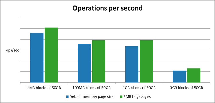
Figure 7: Hugepage operations per second comparison
6 NUMA Awareness
6.1 Description
NUMA, or non-uniform memory access, describes a system with more than one system bus. CPU resources and memory resources are grouped together into a NUMA node. Communication between a CPU and memory within a NUMA node is much faster than in an ordinary system layout.
To show the benefits of using NUMA awareness within VMs, sysbench is used.
6.2 Configuration
First, create a flavor that has the NUMA awareness property.
On the Controller node, run:
openstack flavor create numa_aware_flavor --vcpus 4 --disk 20 -- ram \ 4096

openstack flavor set numa_aware_flavor --property \ hw:numa_mempolicy=strict --property hw:numa_cpus.0=0,1,2,3 --property \ hw:numa_mem.0=4096
Create two VMs, one which is NUMA-aware and one which is not NUMA-aware.
On the Controller node, run:
openstack server create --image ubu160410G --flavor numa_aware_flavor \ --nic net-id=e203cb1e-988f-4bb5-bbd1-54fb34783e02 --availability-zone \ nova::silpixa00395293 numa_aware_vm

openstack server create --image ubu160410G --flavor default--nic \ net-id=e203cb1e-988f-4bb5-bbd1-54fb34783e02 --availability-zone \ nova::silpixa00395293 default_vm
The threads mode and the memory mode of sysbench are utilized in order to benchmark these VMs.
To install sysbench, log into the VMs created above, and run the following command:
sudo apt install sysbench
From the VMs run the following commands.
The command to benchmark threads is:
sysbench --test=threads --num_thread=256 --thread-wields=10000 \ --thread-locks=128 run
The command to benchmark memory is:
sysbench --test=memory --memory-block-size=1K --memory-total-size=50G \ run
6.3 Performance benefit
The graph below shows that there is an increase in both thread and memory using the benchmark described above, when the NUMA awareness property is set.
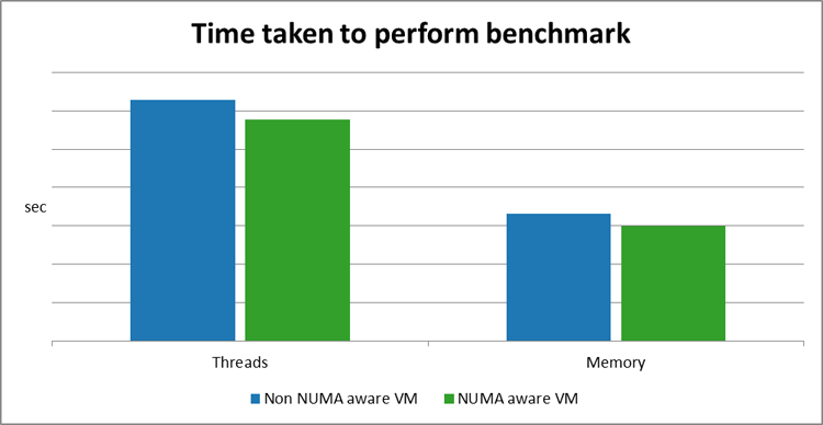
Figure 8: NUMA awareness benchmarks
7 I/O Based NUMA Scheduling
The NUMA awareness feature described in section 5 details how to request a guest NUMA topology that matches the host NUMA topology. This ensures that all memory accesses are local to the NUMA node, and thus not consuming the very limited cross-node memory bandwidth, which adds latency to memory accesses.
However, this configuration does not take into consideration the locality of the I/O device providing data to the guest processing cores. For example, if guest vCPU cores are assigned to a particular NUMA node, but the NIC transferring the data is local to another NUMA node; this will result in reduced application performance.
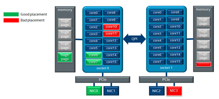
Figure 9 Guest NUMA placement considerations
The above diagram highlights two guest placement configurations. With the good placement configuration the guest physical CPU (pCPU) cores, memory allocation, and PCI device are all associated with the same NUMA node.
An optimal configuration would be where the guests assigned PCI device, RAM allocation, and assigned pCPU are associated with the same NUMA node. This will ensure that there is no cross-NUMA node memory traffic.
The configuration for this feature is similar to the configuration for PCI passthrough, described in sections 3.1 and 3.2
NOTE: In section 3 a single NUMA node is requested for the guest, and its vCPU is bound to host NUMA node 0:
openstack flavor set <FLAVOR> --property  hw:numa_nodes=1
openstack flavor set <FLAVOR> --property  hw:numa_cpus.0=0
If the platform has only one PCI device and it is associated with NUMA node 1, the guest will fail to boot.
7.1 Benefit
The advantage of this feature is that the guest PCI device and pCPU’s cores are all associated with the same NUMA node, avoiding cross-node memory traffic. This can deliver a significant improvement in network throughput, especially for smaller packets.
To demonstrate the benefit of this feature, the network throughput of guest A, that uses a PCI NIC that is associated with the same NUMA node, and the network throughput of guest B, that uses a PCI NIC that is associated with a remote NUMA node, is compared.

Figure 10: NUMA awareness throughput comparison
8 Configure Open vSwitch
8.1 Description
When deploying OpenStack, vanilla Open vSwitch (OVS) is the default virtual switch used by OpenStack.
OVS comes as standard in most, if not all, OpenStack deployment tools such as Mirantis Fuel* and OpenStack Devstack.
8.1.1 Configure the controller node
Devstack deploys OpenStack based on a local.conf file. The details required by the local.conf file will change, based on your system, but an example for the Controller node is shown below:
OVS_LOG_DIR=/opt/stack/logs
OVS_BRIDGE_MAPPINGS="default:<bridge-name>"
PUBLIC_BRIDGE=br-ex
8.1.2 Configure the compute node
The parameters required for the Compute node are almost identical. Simply remove the public_bridge parameter:
OVS_LOG_DIR=/opt/stack/logs
OVS_BRIDGE_MAPPINGS="default:<bridge-name>"
To test vanilla OVS create a VM on the Compute Host, and use a traffic generator to send traffic to the VM. Have it sent back out through the host to the generator, and note the throughput.
The VM requires two networks to be connected to it in order for traffic to be sent up and then come back down. By default, OpenStack creates a single network which is usable by VMs on the host; that is, private.
Create a second network and subnet for the second NIC, and attach the subnet to the preexisting router:
openstack network create private2 --availability-zone nova
openstack subnet create subnet2 --network private2 --subnet-range \ 11.0.0.0/24
openstack router add subnet router1 subnet2
When that is done create the VM:
openstack server create --image ubu160410G --flavor m1.small --nic \ net-id=<private_net_id> --nic net-id=<private2_net_id> \ --security-group default --availability-zone nova::<compute_hostname> \ vm_name
Now, configure the system to forward packets from the packet generator through the VMs and back to Ixia*.
The setup for this is explained in detail in the section below, called Configure packet forwarding test with two virtual networks.
8.2 OVS-DPDK
8.2.1 Description
OVS-DPDK will be used to see how much of an increase in performance is received over vanilla OVS. To utilize OVS-DPDK you will need to set it up. In this case, OpenStack Devstack is used, and changing from vanilla OVS to OVS-DPDK requires some parameters to be changed within the local.conf file, and it requires you to restack the node.
For this test, send traffic from the Ixia traffic generator through the VM hosted on the Compute node and back to Ixia. In this test case, OVS-DPDK only needs to be set up on the Compute node.
8.2.2 Configure the compute node
Within the local.conf file add the specific parameters as shown below:
OVS_DPDK_MODE=compute
OVS_NUM_HUGEPAGES=<num-hugepages>
OVS_DATAPATH_TYPE=netdev
#Create the OVS Openstack management bridge and give it a name
OVS_BRIDGE_MAPPINGS="default:<bridge>"
#Select the interfaces you wish to be handled by DPDK
OVS_DPDK_PORT_MAPPINGS=”<interface>:<bridge>”,”<interface2>:<bridge>”
Now restack the Compute node. Once that is complete, the setup can be benchmarked.
8.2.3 Configure the controller node
You need two networks connected to the VM in order for traffic to be sent up and then come back down. By default, OpenStack creates a single network that is usable by VMs on the host; that is, private. A second network and subnet must be created for the second NIC, and attach the subnet to the preexisting router.
On the Controller node, run:
openstack network create private2 --availability-zone nova
openstack subnet create subnet2 --network private2 --subnet-range \ 11.0.0.0/24
openstack router add subnet router1 subnet2
Once that is done, create the VM. To utilize DPDK the VM must use hugepages. Details on how to set up your Compute node to use hugepages are given in the “Hugepage Support” section.
On the Controller node run:
openstack server create --image ubu160410G --flavor hugepage_flavor \ --nic net-id=<private_net_id> --nic net-id=<private2_net_id> \ --security-group default --availability-zone nova::<compute_hostname> \ vm_name
Now configure the system to forward packets from Ixia through the VMs and back to Ixia. The setup for this is explained in detail in the section below, called Configure packet forwarding test with two virtual networks.
Once that is complete run traffic through the Host.
8.3 Performance Benefits
The graph below highlights the performance gain when using a DPDK accelerated OVS.

Figure 11: Virtual switch throughput comparison
9 CPU Pinning
9.1 Description
CPU pinning allows a VM to be pinned to specific CPUs without worrying about being moved around by the kernel scheduler. This increases the performance of the VM while the host is under heavy load. Its processes will not be moved from CPU to CPU, and instead they will be run within the pinned CPUs.
9.2 Configuration
There are two ways to use this feature in Newton, either by editing the properties of a flavor, or editing the properties of an image file. Both are shown below.
openstack flavor set <FLAVOR_NAME> --property hw:cpu_policy=dedicated
openstack image set <IMAGE_ID> --property hw_cpu_policy=dedicated
For the following test the Ixia traffic generator is connected to the Compute Host. Two VMs with two vNICs are needed; one VM with core pinning enabled and one with it disabled. Two separate flavors were created with the only difference being the cpu_policy.
On the Controller node run:
openstack flavor create un_pinned --ram 4096 --disk 20 --vcpus 4
openstack flavor create pinned --ram 4096 --disk 20 --vcpus 4
There is no need to change the policy for the unpinned flavor as the default cpu_policy is ‘shared’. For the pinned flavor set the cpu_policy to ‘dedicated’.
On the Controller node run:
openstack flavor set pinned --property hw:cpu_policy=dedicated
Create a network and subnet for the second NIC and attach the subnet to the preexisting router.
On the Controller node, run:
openstack network create private2 --availability-zone nova
openstack subnet create subnet2 --network private2 --subnet-range \ 11.0.0.0/24
openstack router add subnet router1 subnet2
Once this is complete create two VMs; one with core pinning enabled and one without.
On the Controller node, run:
openstack server create --image ubu160410G --flavor pinned --nic \ net-id=<private_net_id> --nic net-id=<private2_net_id> \ --security-group default --availability-zone nova::<compute_hostname> pinnedvm

openstack server create --image ubu160410G --flavor un_pinned --nic \ net-id=<private_net_id> --nic net-id=<private2_net_id> \ --security-group default --availability-zone nova::<compute_hostname> defaultvm
Now, configure the system to forward packets from Ixia through the VMs and back to Ixia. The setup for this is explained in detail in the section below, called Configure packet forwarding test with two virtual networks. Send traffic through both VMs while the host is idle and also while it is under stress, and graph the results. Use the Linux* ‘stress’ command. To do this, install stress on the Compute Host.
On Ubuntu simply run:
sudo apt-get install stress
The test run command in this benchmark is shown here:
stress --cpu 56 --io 4 --vm 2 --vm-bytes 128M --timeout 60s&
9.3 Performance benefit
The graph below highlights the performance gain when using the CPU pinning feature.

Figure 12: CPU pinning throughput comparison
10 CPU Thread Policies
10.1 Description
CPU thread policies work with CPU pinning to ensure that the performance of your VM is maximized. CPU thread policy isolate allows entire physical cores to be allocated for use by a VM. While CPU pinning alone may allow Intel® Hyper-Threading Technology (Intel® HT Technology) siblings to be used by different processes, thread policy isolate ensures that this cannot happen. It also ensures that a physical core does not have more than one process trying to access it at one time. Similar to how CPU pinning was benchmarked, start by creating a new OpenStack flavor.
10.2 Configuration
On the Controller node, run:
openstack flavor create pinned_thread_policy --ram 4096 --disk 20 \ --vcpus 4
Thread policies were created to work with CPU pinning, so add both CPU pinning and thread policies to this flavor.
On the Controller node, run:
openstack flavor set pinned_with_thread --property \ hw:cpu_policy=dedicated --property hw:cpu_thread_policy=isolate
As is the case in the Pinning benchmark above, a second private network is needed to test this feature.
On the Controller node, run:
openstack network create private2 --availability-zone nova
openstack subnet create subnet2 --network private2 --subnet-range \ 11.0.0.0/24
openstack router add subnet router1 subnet2
Now create the VM. This VM is benchmarked versus the two VMs created in the previous section.
On the Controller node, run:
openstack server create --image ubu160410G --flavor pinned_with_thread \ --nic net-id=<private_net_id> --nic net-id=<private2_net_id> \ --security-group default --availability-zone nova::<compute_hostname> \ pinned_thread_vm
Ensure that the system is configured to forward traffic from Ixia through the VM and back to Ixia; read the section Configure packet forwarding test with two virtual networks. Send traffic through the VM while the host is idle and while it is under stress. Use the Linux ‘stress’ command. To do this, install stress on the Compute Host:
sudo apt-get install stress
On the Compute Host run the following command:
stress --cpu 56 --io 4 --vm 2 --vm-bytes 128M --timeout 60s&
10.3 Performance benefit
The graph below shows that a pinned VM actually performs slightly better than the other VMs while the system is unstressed. However, when the system is stressed there is a large increase in performance for the thread isolated VM over the pinned VM.
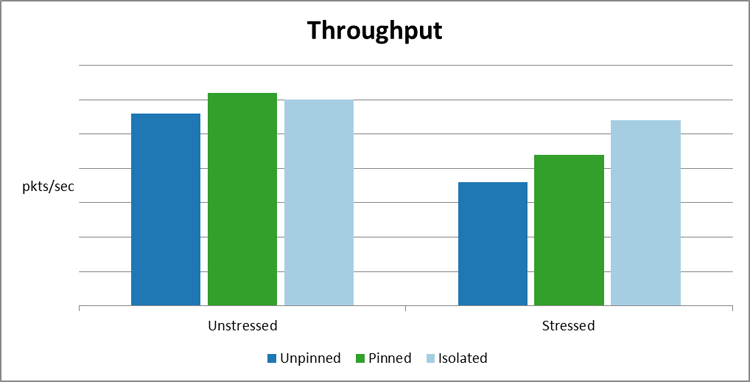
Figure 13: CPU thread policy through comparison
11 Appendix
This section details some learning we came across while working on this paper.
11.1 Configure packet forwarding test with two virtual networks
This section details the setup for testing throughput in a VM. Here we use standard OVS and L2 forwarding in the VM.
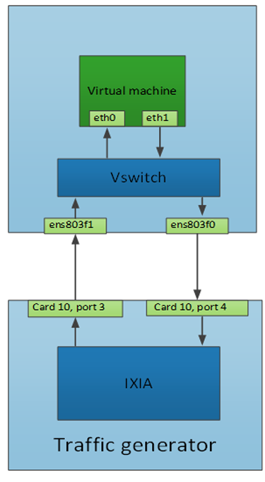
Figure 14: Packet forwarding test topology
11.1.2 Host configuration
Standard OVS deployed by OpenStack uses two bridges: a physical bridge (br-ens787f1) to plug the physical NICs into, and an integration bridge (br-int) that the VM VNICs get plugged into.
Plug in physical NICs:
sudo ovs-vsctl add-port br-ens787f1 ens803f1
sudo ovs-vsctl add-port br-ens787f1 ens803f0
Modify the rules on the integration bridge to allow traffic to and from the VM.
First, find out the port numbering in OVS ports on the integration bridge:
sudo ovs-ofctl show br-int
1(int-br-ens787f1): addr:12:36:84:3b:d3:7e
     config:     0
     state:      0
     speed: 0 Mbps now, 0 Mbps max
 4(qvobf529352-2e): addr:b6:34:b5:bf:73:40
     config:     0
     state:      0
     current:    10GB-FD COPPER
     speed: 10000 Mbps now, 0 Mbps max
 5(qvo70aa7875-b0): addr:92:96:06:8b:fe:b9
     config:     0
     state:      0
     current:    10GB-FD COPPER
     speed: 10000 Mbps now, 0 Mbps max
 LOCAL(br-int): addr:5a:c9:6e:f8:3a:40
     config:     0
     state:      0
     speed: 0 Mbps now, 0 Mbps max
There are, however, issues with the default setup. If you attempt to have heavy traffic passed up to the VM and back down to the host through the same connection, OVS may cause an error to occur, which may cause your system to crash. To overcome this you will need to add a second connection from the integration bridge to the physical bridge.
Traffic going to the VM:
sudo ovs-ofctl add-flow br-int priority=10,in_port=1,action=output=4
Traffic coming from the VM:
sudo ovs-ofctl add-flow br-int priority=10,in_port=5,action=output=1
11.1.3 VM configuration
First, make sure there are two NICs up and running. This can be done manually or persistently by editing this file: /etc/network/interfaces
auto ens3
iface ens3 inet dhcp

auto ens4
aface ens4 inet dhcp
Then restart the network:
/etc/init.d/networking restart
Following this step there should be two running NICs in the VM.
By default, a system's routing table has just one default gateway; this will be whichever NIC came up first. To access both VM networks from the host, remove the default gateway. It is possible to add a second routing table to do this, but this is the easiest and quickest way. A downside of this approach is that you will not be able to communicate with the VM from the host, so you can use Horizon* for the remaining steps.
Now, forward the traffic coming in on one NIC to the other NIC. L2 bridging is used for this:
ifconfig ens3 0.0.0.0
ifconfig ens4 0.0.0.0

brctl addbr br0
brctl stp br0 on
brctl addif br0 ens3
brctl addif br0 ens4
brctl show

ifconfig ens3 up
ifconfig ens4 up
ifconfig br0 up
The two VM NICs should now be added to br0.
11.1.4 Ixia configuration
There are two ports on the traffic generator. Let’s call them C10P3 and C10P4.
On C10P3 configure the source and destination MAC and IP
SRC: 00:00:00:00:00:11, DST: 00:00:00:00:00:10
SRC: 11.0.0.100, DST 10.0.0.100
On C10P4 configure the source and destination MAC and IP
SRC: 00:00:00:00:00:10, DST: 00:00:00:00:00:11
SRC: 10.0.0.100, DST 11.0.0.100
As a VLAN network is being used here, VLAN tags must be configured.
Set them to the tags Openstack has given, in this case it's 1208.
Once these steps are complete you can start sending packets to the host, and you can verify that VM traffic is hitting the rules on the integration bridge by running the command:
watch -d sudo ovs-ofctl dump-flows br-int
You should see the packets received and packets sent increase on their respective flows.
11.2 AppArmor* issue
AppArmor* has many security features which may require additional configuration. One such issue is that if you attempt to allocate HugePages to a VM, AppArmor will cause Libvirtd* to give a permission denied message. To get around this, edit the qemu.conf file and change the security driver field, as follows:
vi /etc/libvirt/qemu.conf

security_driver = "none"
11.3 Share host ssh public keys with the guest for direct access
openstack keypair create --public-key ~/.ssh/id_rsa.pub mykey
openstack keypair list
11.4 Add rules to default security group for icmp and ssh access to guests
openstack security group rule create --protocol icmp --ingress default
openstack security group rule create --protocol tcp --dst-port 22 \ --ingress default
openstack security group list
openstack security group show default
11.5 Boot a VM
openstack image list
openstack flavor list
openstack keypair  list
openstack server create --image ubuntu1604 --flavor R4D6C4  --security-group \ default --key-name mykey vm1
openstack server list
11.6 Resize an image filesystem
sudo apt install libguestfs-tools
View your image partitions
sudo virt-filesystems --long -h --all -a ubuntu1604-5G.qcow2
Name       Type        VFS      Label  MBR  Size  Parent
/dev/sda1  filesystem  ext4     -      -    3.0G  -
/dev/sda2  filesystem  unknown  -      -    1.0K  -
/dev/sda5  filesystem  swap     -      -    2.0G  -
/dev/sda1  partition   -        -      83   3.0G  /dev/sda
/dev/sda2  partition   -        -      05   1.0K  /dev/sda
/dev/sda5  partition   -        -      82   2.0G  /dev/sda
/dev/sda   device      -        -      -    5.0G
Here’s how to expand /dev/sda1:
Create a 10G image template:
sudo truncate -r ubuntu1604-5G.qcow2 ubuntu1604-10G.qcow2
Extend the 5G image by 5G:
sudo truncate -s +5G ubuntu1604-10G.qcow2
Resize 5G image to 10G image template:
sudo virt-resize --expand /dev/sda1 /home/tester/ubuntu1604-5G.qcow2 \ /home/tester/ubuntu1604-10G.qcow2
11.7 Expand the filesystem of a running Ubuntu* image
11.7.1 Delete existing partitions
sudo fdisk /dev/sda

Command (m for help): p

Disk /dev/sda: 268.4 GB, 268435456000 bytes
255 heads, 63 sectors/track, 32635 cylinders, total 524288000 sectors
Units = sectors of 1 * 512 = 512 bytes
Sector size (logical/physical): 512 bytes / 512 bytes
I/O size (minimum/optimal): 512 bytes / 512 bytes
Disk identifier: 0x000e49fa

   Device Boot  	Start     	End  	Blocks   Id  System
/dev/sda1   *    	2048   192940031	96468992   83  Linux
/dev/sda2   	192942078   209713151 	8385537	5  Extended
/dev/sda5   	192942080   209713151 	8385536   82  Linux swap / Solaris

Command (m for help): d
Partition number (1-5): 1

Command (m for help): d
Partition number (1-5): 2
11.7.2 Create new partitions
Command (m for help): n
Partition type:
   p   primary (0 primary, 0 extended, 4 free)
   e   extended
Select (default p): p
Partition number (1-4, default 1):
Using default value 1
First sector (2048-524287999, default 2048):
Using default value 2048
Last sector, +sectors or +size{K,M,G} (2048-524287999, default 524287999): 507516925

Command (m for help): n
Partition type:
   p   primary (1 primary, 0 extended, 3 free)
   e   extended
Select (default p): e
Partition number (1-4, default 2): 2
First sector (507516926-524287999, default 507516926):
Using default value 507516926
Last sector, +sectors or +size{K,M,G} (507516926-524287999, default 524287999):
Using default value 524287999

Command (m for help): n
Partition type:
   p   primary (1 primary, 1 extended, 2 free)
   l   logical (numbered from 5)
Select (default p): l
Adding logical partition 5
First sector (507518974-524287999, default 507518974):
Using default value 507518974
Last sector, +sectors or +size{K,M,G} (507518974-524287999, default 524287999):
Using default value 524287999
11.7.3 Change logical partition to SWAP
Command (m for help): t
Partition number (1-5): 5

Hex code (type L to list codes): 82
Changed system type of partition 5 to 82 (Linux swap / Solaris)
11.7.4 View new partitions
Command (m for help): p

Disk /dev/sda: 268.4 GB, 268435456000 bytes
255 heads, 63 sectors/track, 32635 cylinders, total 524288000 sectors
Units = sectors of 1 * 512 = 512 bytes
Sector size (logical/physical): 512 bytes / 512 bytes
I/O size (minimum/optimal): 512 bytes / 512 bytes
Disk identifier: 0x000e49fa

   Device Boot  	Start     	End  	Blocks   Id  System
/dev/sda1        	2048   507516925   253757439   83  Linux
/dev/sda2   	507516926   524287999 	8385537	5  Extended
/dev/sda5   	507518974   524287999 	8384513   82  Linux swap / Solaris
11.7.5 Write changes
Command (m for help): w
The partition table has been altered!
FYI: Ignore any errors or warnings at this point and reboot the system:
sudo reboot
11.7.6 Increase the filesystem size
sudo resize2fs /dev/sda1
11.7.7 Activate SWAP
sudo mkswap /dev/sda5
sudo swapon --all --verbose
swapon on /dev/sda5
11.8 Patch ports
Patch ports can be used to create links between OVS bridges. They are useful when you are running the benchmarks that require traffic to be sent up to a VM and back out to a traffic generator. OpenStack only creates one link between the bridges, and having traffic going up and down the same link can cause issues.
To create a patch port, ‘patch1’, on the bridge ‘br-eno2’, which has a peer called ‘patch2’, do the following:
sudo ovs-vsctl add-port br-eno2 patch1 -- set Interface patch1 \ type=patch options:peer=patch2
To create a patch port, ‘patch2’, on the bridge ‘br-int’, which has a peer called ‘patch1’, do the following:
sudo ovs-vsctl add-port br-int patch2 -- set Interface patch2 \ type=patch options:peer=patch1
12 References
http://docs.openstack.org/juno/config-reference/content/kvm.html
http://docs.openstack.org/mitaka/networking-guide/config-sriov.html