Environment Variables for Process Pinning
I_MPI_PIN
Turn on/off process pinning.
Syntax
I_MPI_PIN=<arg>
Arguments
| <arg> | Binary indicator |
| enable | yes | on | 1 | Enable process pinning. This is the default value. |
| disable | no | off | 0 | Disable process pinning. |
Description
Set this environment variable to control the process pinning feature of the Intel® MPI Library.
I_MPI_PIN_PROCESSOR_LIST (I_MPI_PIN_PROCS)
Define a processor subset and the mapping rules for MPI processes within this subset.
This environment variable is available for both Intel and non-Intel microprocessors, but it may perform additional optimizations for Intel microprocessors than it performs for non-Intel microprocessors.
Syntax Forms
I_MPI_PIN_PROCESSOR_LIST=<value>
The environment variable value has three syntax forms:
- <proclist>
- [<procset> ][:[grain=<grain> ][,shift=<shift> ][,preoffset=<preoffset> ][,postoffset=<postoffset> ]
- [<procset> ][:map=<map> ]
The following paragraphs provide detailed descriptions for each of these syntax forms.
NOTE:
The postoffset keyword has offset alias.
NOTE:
The second form of the pinning procedure has three steps:
- Circular shift of the source processor list on preoffset*grain value.
- Round robin shift of the list derived on the first step on shift*grain value.
- Circular shift of the list derived on the second step on the postoffset*grain value.
NOTE:
The grain, shift, preoffset, and postoffset parameters have a unified definition style.
Syntax 1: <proclist>
I_MPI_PIN_PROCESSOR_LIST=<proclist>
Arguments
| <proclist> | A comma-separated list of logical processor numbers and/or ranges of processors. The process with the i-th rank is pinned to the i-th processor in the list. The number should not exceed the number of processors on a node. |
| <l> | Processor with logical number <l>. |
| <l>-<m> | Range of processors with logical numbers from <l> to <m>. |
| <k>,<l>-<m> | Processors <k>, as well as <l> through <m>. |
Syntax 2: [<procset> ][:[grain=<grain> ][,shift=<shift> ][,preoffset=
I_MPI_PIN_PROCESSOR_LIST=[<procset>][:[grain=<grain>][,shift=<shift>][,preoffset=<preoffset>][,postoffset=<postoffset>]
Arguments
| <procset> | Specify a processor subset based on the topological numeration. The default value is allcores. |
| all | All logical processors. Specify this subset to define the number of CPUs on a node. |
| allcores | All cores (physical CPUs). Specify this subset to define the number of cores on a node. This is the default value. If Intel® Hyper-Threading Technology is disabled, allcores equals to all. |
| allsocks | All packages/sockets. Specify this subset to define the number of sockets on a node. |
| <grain> | Specify the pinning granularity cell for a defined <procset>. The minimal <grain>value is a single element of the <procset>. The maximal <grain> value is the number of <procset> elements in a socket. The <grain>value must be a multiple of the <procset> value. Otherwise, the minimal <grain> value is assumed. The default value is the minimal <grain> value. |
| <shift> | Specify the granularity of the round robin scheduling shift of the cells for the <procset>. <shift>is measured in the defined <grain>units. The <shift>value must be positive integer. Otherwise, no shift is performed. The default value is no shift, which is equal to 1 normal increment. |
| <preoffset> | Specify the circular shift of the processor subset <procset>defined before the round robin shifting on the <preoffset>value. The value is measured in the defined <grain>units. The <preoffset>value must be non-negative integer. Otherwise, no shift is performed. The default value is no shift. |
| <postoffset> | Specify the circular shift of the processor subset <procset>derived after round robin shifting on the <postoffset>value. The value is measured in the defined <grain>units. The <postoffset>value must be non-negative integer. Otherwise no shift is performed. The default value is no shift. |
The following table displays the values for <grain>, <shift>, <preoffset>, and <postoffset> options:
| <n> | Specify an explicit value of the corresponding parameters. <n>is non-negative integer. |
| fine | Specify the minimal value of the corresponding parameter. |
| core | Specify the parameter value equal to the amount of the corresponding parameter units contained in one core. |
| cache1 | Specify the parameter value equal to the amount of the corresponding parameter units that share an L1 cache. |
| cache2 | Specify the parameter value equal to the amount of the corresponding parameter units that share an L2 cache. |
| cache3 | Specify the parameter value equal to the amount of the corresponding parameter units that share an L3 cache. |
| cache | The largest value among cache1, cache2, and cache3. |
| socket | sock | Specify the parameter value equal to the amount of the corresponding parameter units contained in one physical package/socket. |
| half | mid | Specify the parameter value equal to socket/2. |
| third | Specify the parameter value equal to socket/3. |
| quarter | Specify the parameter value equal to socket/4. |
| octavo | Specify the parameter value equal to socket/8. |
Syntax 3: [<procset> ][:map=<map> ]
I_MPI_PIN_PROCESSOR_LIST=[<procset>][:map=<map>]
Arguments
| <map> | The mapping pattern used for process placement. |
| bunch | The processes are mapped proportionally to sockets and the processes are ordered as close as possible on the sockets. |
| scatter | The processes are mapped as remotely as possible so as not to share common resources: FSB, caches, and core. |
| spread | The processes are mapped consecutively with the possibility not to share common resources. |
Description
Set the I_MPI_PIN_PROCESSOR_LIST environment variable to define the processor placement. To avoid conflicts with different shell versions, the environment variable value may need to be enclosed in quotes.
NOTE:
This environment variable is valid only if I_MPI_PIN is enabled.
The I_MPI_PIN_PROCESSOR_LIST environment variable has the following different syntax variants:
- Explicit processor list. This comma-separated list is defined in terms of logical processor numbers. The relative node rank of a process is an index to the processor list such that the i-th process is pinned on i-th list member. This permits the definition of any process placement on the CPUs.
For example, process mapping for I_MPI_PIN_PROCESSOR_LIST=p0,p1,p2,...,pn is as follows:
Rank on a node 0 1 2 ... n-1 N Logical CPU p0 p1 p2 ... pn-1 Pn - grain/shift/offset mapping. This method provides circular shift of a defined grain along the processor list with steps equal to shift*grain and a single shift on offset*grain at the end. This shifting action is repeated shift times.
For example: grain = 2 logical processors, shift = 3 grains, offset = 0.
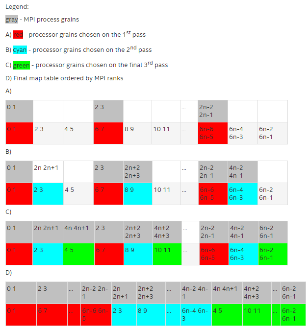
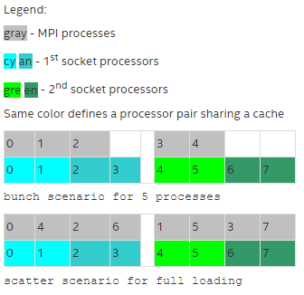
- Predefined mapping scenario. In this case, popular process pinning schemes are defined as keywords selectable at runtime. There are two such scenarios: bunch and scatter.
In the bunch scenario the processes are mapped proportionally to sockets as closely as possible. This mapping makes sense for partial processor loading. In this case, the number of processes is less than the number of processors.
In the scatter scenario the processes are mapped as remotely as possible so as not to share common resources: FSB, caches, and cores.
In the example, there are two sockets, four cores per socket, one logical CPU per core, and two cores per shared cache.
Examples
To pin the processes to CPU0 and CPU3 on each node globally, use the following command:
$ mpirun -genv I_MPI_PIN_PROCESSOR_LIST=0,3 -n <number-of-processes> <executable>
To pin the processes to different CPUs on each node individually (CPU0 and CPU3 on host1 and CPU0, CPU1 and CPU3 on host2), use the following command:
$ mpirun -host host1 -env I_MPI_PIN_PROCESSOR_LIST=0,3 -n <number-of-processes> <executable> : \
-host host2 -env I_MPI_PIN_PROCESSOR_LIST=1,2,3 -n <number-of-processes> <executable>
To print extra debugging information about process pinning, use the following command:
$ mpirun -genv I_MPI_DEBUG=4 -m -host host1 \
-env I_MPI_PIN_PROCESSOR_LIST=0,3 -n <number-of-processes> <executable> :\
-host host2 -env I_MPI_PIN_PROCESSOR_LIST=1,2,3 -n <number-of-processes> <executable>
NOTE:
If the number of processes is greater than the number of CPUs used for pinning, the process list is wrapped around to the start of the processor list.
I_MPI_PIN_PROCESSOR_EXCLUDE_LIST
Define a subset of logical processors to be excluded for the pinning capability on the intended hosts.
Syntax
I_MPI_PIN_PROCESSOR_EXCLUDE_LIST=<proclist>
Arguments
| <proclist> | A comma-separated list of logical processor numbers and/or ranges of processors. |
| <l> | Processor with logical number <l>. |
| <l>-<m> | Range of processors with logical numbers from <l>to <m>. |
| <k>,<l>-<m> | Processors <k>, as well as <l>through <m>. |
Description
Set this environment variable to define the logical processors that Intel® MPI Library does not use for pinning capability on the intended hosts. Logical processors are numbered as in /proc/cpuinfo.
I_MPI_PIN_CELL
Set this environment variable to define the pinning resolution granularity. I_MPI_PIN_CELL specifies the minimal processor cell allocated when an MPI process is running.
Syntax
I_MPI_PIN_CELL=<cell>
Arguments
| <cell> | Specify the resolution granularity |
| unit | Basic processor unit (logical CPU) |
| core | Physical processor core |
Description
Set this environment variable to define the processor subset used when a process is running. You can choose from two scenarios:
- all possible CPUs in a node (unit value)
- all cores in a node (core value)
The environment variable has effect on both pinning types:
- one-to-one pinning through the I_MPI_PIN_PROCESSOR_LIST environment variable
- one-to-many pinning through the I_MPI_PIN_DOMAIN environment variable
The default value rules are:
- If you use I_MPI_PIN_DOMAIN, the cell granularity is unit.
- If you use I_MPI_PIN_PROCESSOR_LIST, the following rules apply:
- When the number of processes is greater than the number of cores, the cell granularity is unit.
- When the number of processes is equal to or less than the number of cores, the cell granularity is core.
NOTE:
The core value is not affected by the enabling/disabling of Intel® Hyper-Threading Technology in a system.
I_MPI_PIN_RESPECT_CPUSET
Respect the process affinity mask.
Syntax
I_MPI_PIN_RESPECT_CPUSET=<value>
Arguments
| <value> | Binary indicator |
| enable | yes | on | 1 | Respect the process affinity mask. This is the default value. |
| disable | no | off | 0 | Do not respect the process affinity mask. |
Description
If you set I_MPI_PIN_RESPECT_CPUSET=enable, the Hydra process launcher uses job manager's process affinity mask on each intended host to determine logical processors for applying Intel MPI Library pinning capability.
If you set I_MPI_PIN_RESPECT_CPUSET=disable, the Hydra process launcher uses its own process affinity mask to determine logical processors for applying Intel MPI Library pinning capability.
I_MPI_PIN_RESPECT_HCA
In the presence of Infiniband architecture* host channel adapter (IBA* HCA), adjust the pinning according to the location of IBA HCA.
Syntax
I_MPI_PIN_RESPECT_HCA=<value>
Arguments
| <value> | Binary indicator |
| enable | yes | on | 1 | Use the location of IBA HCA if available. This is the default value. |
| disable | no | off | 0 | Do not use the location of IBA HCA. |
Description
If you set I_MPI_PIN_RESPECT_HCA=enable , the Hydra process launcher uses the location of IBA HCA on each intended host for applying Intel MPI Library pinning capability.
If you set I_MPI_PIN_RESPECT_HCA=disable, the Hydra process launcher does not use the location of IBA HCA on each intended host for applying Intel MPI Library pinning capability.
Parent topic: Process Pinning