The new Intel® Arc™ GPUs (formerly code named Alchemist) fully support the DirectX* 12 Ultimate feature set including variable-rate shading (VRS), mesh shading and DirectX* Raytracing (DXR). Support for DXR and real-time ray tracing (RTRT) comes through new hardware acceleration blocks built into Intel® Arc™ GPUs. This developer guide describes RTRT applications and contains details developers need to fully incorporate this technology in their titles.
This document is organized in two parts. The first part presents a functional description of Intel’s ray-tracing implementation, to provide developers with an accurate mental model. The second part provides a concrete, quotable list of guidelines for developers to maximize performance for RTRT applications.
The following diagram illustrates the data and control flow in Intel’s ray-tracing implementation. The diagram shows an abstract view of the Xe-core, which is the scalability unit for the Xe-HPG GPU architecture, and dedicated accelerating hardware. Each Xe-core contains a number of Vector Engines (XVEs). These are Single Instruction Multiple Data (SIMD) compute units which execute ray-tracing shaders in groups of 8 or 16 shader threads. There is a dedicated hardware block attached to each Xe-core, the ray-tracing unit (RTU) which handles accelerated structure traversal, ray-triangle intersection, ray-box intersection, instance transformations, and hit-shader dispatch. The traversal and intersection hardware will operate on individual rays and will be multithreaded to facilitate latency hiding.
Real-Time Ray Tracing Functional Overview
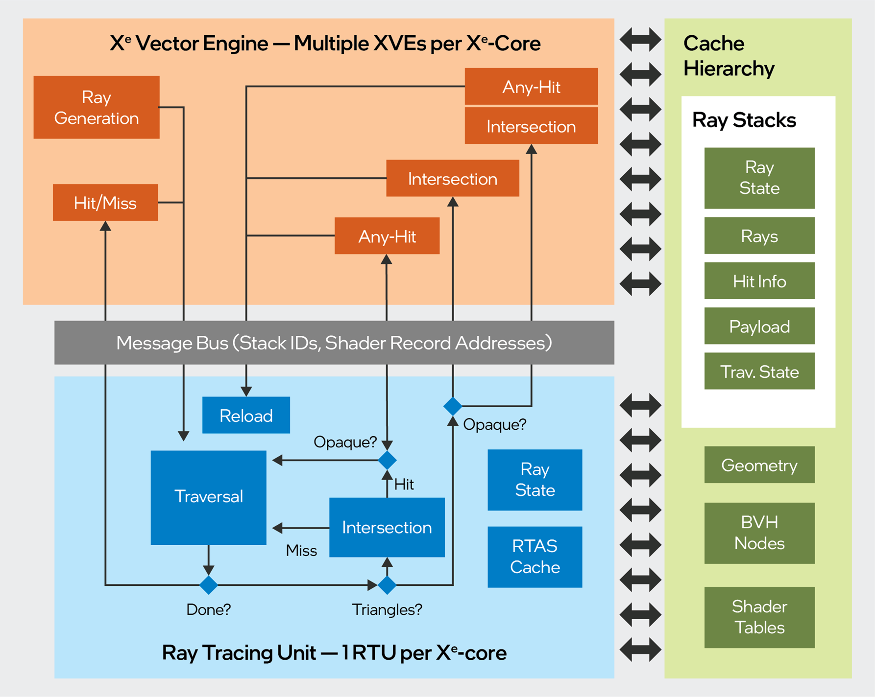
Figure 1. Data and control flow in Intel’s ray-tracing implementation
In our implementation, the ray-tracing process is a synchronized flow between the ray-tracing shaders, which execute on the XVE, and scene traversal, which executes in the RTU. To initiate ray tracing, a ray-generation shader running on the XVE writes ray data to memory, and sends a SIMD TraceRay message to the RTU. The TraceRay message specifies one ray for each active SIMD lane. After sending the TraceRay message, the XVE thread will terminate, so that it is available for hit-shader execution, if necessary (refer to Understanding Bucketed Thread Dispatch for more details). Hit shaders are dispatched by the hardware, one ray at a time. The Thread Shorting Unit (TSU) is used to coalesce these individual rays into coherent SIMD groups. During this process the TSU hardware also sorts the rays by shader-record address in order to extract as much SIMD coherence as possible.
Each ray-generation shader thread has an associated stack, which is a dedicated block of driver-allocated memory. The stack is used to store data across shader invocations, and for communication between the XVEs and the RTU (via the L1 cache). The driver allocates a fixed set of stacks, and hardware allocates them to ray-generation threads as they are launched.
During traversal, the entire state of a ray is maintained in dedicated registers within the RTU. Upon receipt of a traversal message, the hardware will read ray data from the ray’s stack, and initialize the traversal state registers. The state will be maintained in registers throughout traversal, until hardware determines that a shader must be run. At that point, the current state of the ray (object-space origin/direction, current instance, hit information) is written out to the ray stack, and its registers are re-allocated to service another incoming ray. The RTU is stateless, in that it does not continue to track rays once they have reached a shader execution point, and transitioned back to the XVE.
For any-hit and intersection shaders, the ray’s internal traversal state is also written to memory, and the compiler will send a TraceRay_Continue message at the end of the shader to restart traversal. Upon receiving a TraceRay_Continue message, hardware will reload the traversal state from memory instead of initializing it, so that the earlier traversal is resumed where it left off.
Note that all cross-stage communication is via cached memory. At launch time, each hit-shader thread receives a 16-bit stack ID, a shader-record pointer for fetching local arguments, and a global pointer for fetching global root arguments. All other data is read and written by XVEs and RTU hardware, as required. In our implementation, the minimum memory footprint for a single DXR ray is 256 bytes. This assumes no ray payload, no recursion, and no use of intersection shaders.
Note that for procedural hit groups, the any-hit and intersection shaders will be merged at compile time. If a workload already utilizes an intersection shader, any-hit shaders can be added without additional thread dispatch overhead. In the case of an intersection shader paired with an any-hit shader, the Intel® Graphics driver will compile opaque and non-opaque variants of the intersection shader for each hit group. In the opaque variant, the intersection shader will simply track the closest hit, store it back to memory, and update the ray’s trace-distance value. In the nonopaque variant, the any-hit shader will be inlined into the intersection shader, and invoked directly during each call to ReportHit(). This is the only likely scenario in which cross-stage communication can occur without passing data through the cache hierarchy.
Understanding the Thread Sorting Unit
Intel Arc GPUs incorporate a new hardware block called the thread sorting unit (TSU) to implement DXR shader dispatch. The TSU is a dedicated hardware block which is able to sort and re-emit shader threads to maximize SIMD coherence from divergent workloads. The operation of thread sorting is illustrated below:
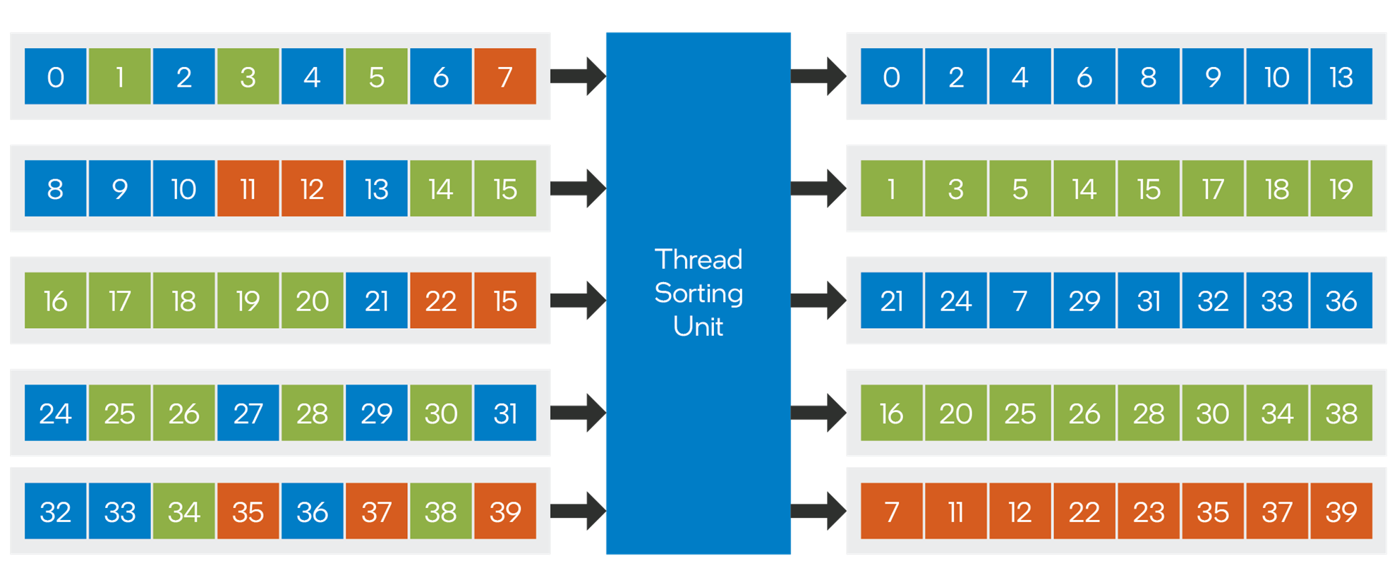
Figure 2. The thread sorting unit (TSU) is a dedicated hardware block that implements DXR shader dispatch.
In the above diagram, five XVE threads are shown executing callable shaders. The different colors denote different target shader records. The numbers on the squares indicate the stack ID for the corresponding thread. The stack ID is a 16-bit identifier which is used to recognize a particular work item across a sequence of bucketed dispatches.
When an XVE thread wishes to dispatch a callable shader, it will send a Bucketed Dispatch message to the TSU, passing the stack ID and a 64-bit shader record address for each active SIMD lane. The TSU will bin the stack IDs by shader record address. It can then emit coherent XVE threads as they are formed, all of which will be the same shader, and share the same shader records. During binning, the stack IDs and shader-record addresses are stored in an on-chip sorting cache. Entries are evicted from the sorting cache whenever a full set of stack IDs is accumulated. If the workload is highly divergent, partially filled threads may need to be evicted in order to guarantee forward progress. Partially filled threads may also be evicted after a specified number of clock cycles, to prevent starvation at the tail end of a workload.
Ray-tracing shaders are implemented using the same machinery, except that the dispatches are performed individually by the ray tracing hardware. For ray tracing shaders, the RTU receives a stack ID per ray as part of the trace message. When the hardware issues a shade request, it will forward this stack ID to the TSU together with the computed shader record address. For hit groups, which contain multiple types of shaders, the shader identifier will consist of a set of instruction pointers in a predefined order, and hardware will offset the shader record pointer based on shader type, before sending the dispatch to the TSU.
At launch time, each hit-shader instance receives a 16-bit stack ID, a pointer to the shader record, which is used to fetch local arguments, and a global pointer which is used to access the global root signature, stack base address, dispatch dimensions, and other global constants. All other data is read and written by XVEs and ray-tracing hardware, as required.
TSU dispatches are always scheduled to the same Xe-core as their parent shader, which means that a given child shader is restricted to a set of approximately 1K SIMD lanes. For extremely “bursty” workloads with unbalanced thread runtimes, multipass techniques using indirect dispatch may be more efficient than callable shaders, because they enable more effective load balancing.
The TSU does not support work amplification, or concurrent execution between parent and child threads. Any thread which performs a CallShader() or TraceRay() must immediately terminate after sending the corresponding message. This is necessary to handle the corner case in which all other threads are fully loaded with other work, and the hardware must reuse the parent thread to execute child shaders.
Whenever a TSU repacking point is encountered, the compiler will spill all live states to the ray’s stack, send the corresponding message, and terminate the thread. To emulate return semantics, the compiler will also push the address of a continuation shader record. Downstream shaders will be required to perform a dispatch back to the continuation shader record, which will reload the live state from the stack and execute the remainder of the parent shader. Figure 3 illustrates this flow:
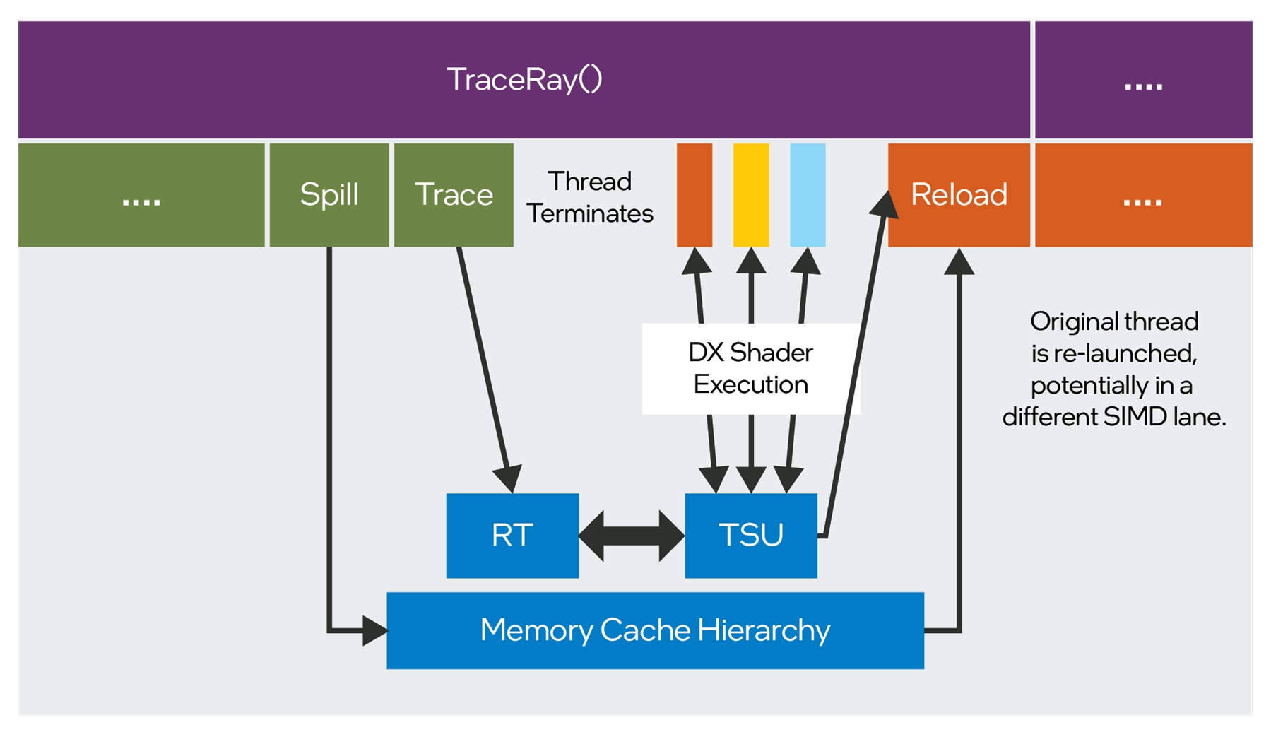
Figure 3. Programming model for DXR.
As can be seen in Figure 3, while the programming model for DXR presents the appearance of simple, sequential shader code within a single thread, the dynamic execution reality can be quite different. It is very important to comprehend this in shader code. For best performance, it is recommended to perform as much work as possible locally in DXR hit shaders, and to minimize ray payload size. It is also essential to avoid keeping a large number of values (large payload) live across a TraceRay() call. If possible, TraceRay() calls should ideally be tail recursive, as this will result in no live values by definition.
The following code sample illustrates an undesirable TraceRay() call. There is excessive data communicated between shaders using the ray payload, and the 'TraceRay' call is not tail recursive.
The value of 'color' must be saved and restored across the TraceRay() call.
struct MyRayPayload
{
	float3 hit_position;
	float3 normal;
	float3 diffuse_color;
	bool was_hit;
};


[shader("closesthit")]
void chs_main( inout MyRayPayload pl )
{
	pl.hit_position = ComputeHitPosition();
	pl.normal = ComputeNormal();
	pl.diffuse_color = ComputeDiffuseColor();
	pl.was_hit = true;
}


[shader("miss")]
void miss_main( inout MyRayPayload pl )
{
	pl.was_hit = false;
}

RWTexture2D<float3> render_target;

[shader("raygeneration")]
void main( )
{
	MyRayPayload pl;
	float3 color = render_target.Load( DispatchRaysIndex().xy );
	TraceRay( ... ray, pl );

	if( pl.was_hit )
		color += DoLighting( pl.hit_position, pl.normal, pl.diffuse_color );
	else
		color += ComputeMissColor(ray.Origin,ray.Direction);

	render_target.Store( DispatchRaysIndex().xy, pl.color );
}


//For contrast, the next code sample shows an optimized implementation of the same algorithm. The ray payload is as small as possible, data is not communicated between shader stages, the was_hit value is completely eliminated, and there is no need for control to return back to the ray generation shader.

struct MyRayPayload
{
	// note the use of a lower precision data type to reduce payload size
	float16_t3 color;
};

RWTexture2D<float3> render_target;

[shader("closesthit")]
void chs_main( inout MyRayPayload pl )
{
	float3 hit_position = ComputeHitPosition();
	float3 normal = ComputeNormal();
	float3 diffuse_color = ComputeDiffuseColor();
	float3 lighting = DoLighting( pl.hit_position,pl.normal,pl.diffuse_color );
	render_target.Store( DispatchRaysIndex().xy, pl.color + lighting );
}

[shader("miss")]
void miss_main( inout MyRayPayload pl )
{
	float3 miss_color = ComputeMissColor(WorldRayOrigin(),WorldRayDirection());
	render_target.Store( DispatchRaysIndex().xy, pl.color + miss_color );
}


[shader("raygeneration")]
void main( )
{
	MyRayPayload pl;
	pl.color = render_target.Load( DispatchRaysIndex().xy );
	TraceRay( ... ray, pl );
}
For contrast, the next code sample shows an optimized implementation of the same algorithm. The ray payload is as small as possible, data is not communicated between shader stages, the was_hit value is completely eliminated, and there is no need for control to return back to the ray generation shader.
struct MyRayPayload
{
	// note the use of a lower precision data type to reduce payload size
	float16_t3 color;
};


RWTexture2D<float3> render_target;

[shader("closesthit")]
void chs_main( inout MyRayPayload pl )
{
	float3 hit_position = ComputeHitPosition();
	float3 normal = ComputeNormal();
	float3 diffuse_color = ComputeDiffuseColor();
	float3 lighting = DoLighting( pl.hit_position,pl.normal,pl.diffuse_color );
	render_target.Store( DispatchRaysIndex().xy, pl.color + lighting );
}


[shader("miss")]
void miss_main( inout MyRayPayload pl )
{
	float3 miss_color = ComputeMissColor(WorldRayOrigin(),WorldRayDirection());
	render_target.Store( DispatchRaysIndex().xy, pl.color + miss_color );
}


[shader("raygeneration")]
void main( )
{
	MyRayPayload pl;
	pl.color = render_target.Load( DispatchRaysIndex().xy );
	TraceRay( ... ray, pl );
}
Ray Tracing Intrinsic Implementation Details
At launch time, each hit-shader thread receives a 16-bit stack ID, a pointer to the shader record, and a global pointer which is used to access the global root signature, stack base address, dispatch dimensions, and other global constants. All other data is read and written by VEs and RTRT hardware, as required.
Ray payloads and intersection attributes all map to cached memory reads and writes. Hardware will write hit information and transformed rays into designated locations in the ray stack memory, which software can read. TraceRay() shader intrinsics will write the entire ray to the stack before sending the trace message and terminating the thread, as described in the Understanding the Thread Sorting Unit section. CallShader() is handled in the same way, but it writes considerably less data.
All of the ray and hit-info accessors will map to loads from the ray stack memory. In some cases, there will also be arithmetic logic unit (ALU) instructions to unpack from bit-fields. Where possible, the compiler will vectorize the loads (for example, calling WorldRayOrigin() will emit a three-channel untyped read message).
The following DXR shader intrinsics are implemented as loads from the ray stack memory:
- DispatchRaysIndex()
- DispatchRaysDimensions() (This maps to a load from a wave-uniform location)
- RayTMin()
- RayTCurrent()
- RayFlags()
- HitKind()
- PrimitiveIndex()
- WorldRayOrigin()
- WorldRayDirection()
The implementations of the following intrinsics depend on the shader type:
- ObjectRayOrigin()
- ObjectRayDirection()
For intersection and any-hit shaders, the object-space ray is available on the ray stack during traversal, and these intrinsics will simply load it. For closest-hit shaders, the values are computed on the fly by multiplying the world-space values by the WorldToObject transform matrix.
Implementing the DXR instance data accessors requires two levels of indirection; the first to read an instance pointer from the ray stack, and the second to access the required data. The compiler will amortize the instance pointer lookup over calls to different intrinsics. For example, calling two different instance intrinsics will typically result in, at most, three load instructions.
- InstanceIndex()
- InstanceID()
- WorldToObject3x4/4x3()
- ObjectToWorld3x4/4x3()
The CallShader() and TraceRay() intrinsics will write ray parameters to the ray stack, spill any live values, send corresponding messages to the TSU or the RTU, and terminate the thread. The thread will be restarted by a continuation dispatch as discussed in the Understanding the Thread Sorting Unit section.
Any-hit shaders have access to two different sets of hit information from the ray stack. There is a potential hit, which is the current hit being considered by the shader, and a committed hit, which is the last hit which was accepted for the ray. The RTU automatically writes these hit records to memory whenever they need to change.
The AcceptHitAndEndSearch() intrinsic will do the following:
- Copy the potential hit into the committed hit
- Send a TSU dispatch for the closest-hit shader in the current shader record
- Terminate the thread
If control reaches the end of an any-hit shader, the following actions take place:
- A commit message is sent to the RTU
- The thread terminates
The IgnoreHit() intrinsic will send a ”continue” message and terminate the thread.
Intel’s RTRT implementation will inline the any-hit shaders into the intersection shaders. Each call to the ReportHit() intrinsic will invoke the any-hit shader (if any) and write the hit attributes to memory if the hit was accepted. When executing from an intersection shader, the IgnoreHit() intrinsic will simply branch back to the intersection shader. AcceptHitAndEndSearch() will terminate the intersection shader thread.
Pipeline-Level Compiler Optimizations
The DXR API requires applications to enumerate all possible shaders that might be used with a given ray-tracing pipeline, and to specify the maximum recursion depth. There are a variety of possible link-time optimizations which the driver and compiler may perform, as appropriate. These include, but are not limited to:
- Inlining hit/miss shaders into return continuations (or vice versa)
- Code motion between shader stages to reduce payload sizes or spills
- Eliminating unnecessary stores to initialize ray payloads
- Eliminating stores of continuation addresses and inlining them if there is only one return site
- Optimizing out stack manipulation code if the recursion depth is known to be 1
- Specializing shaders based on recursion depth
- Skipping hit shader compilation if all TraceRay() calls use particular ray flags
- For example, if all traces use SKIP_CLOSEST_HIT, the compiler can strip out the closest hit shaders
- Forcing an opaque ray flag if no any-hit shaders are used in the pipeline
- Calculating optimal stack sizes based on global optimizations
In order to give the compiler maximum freedom for optimization, it is recommended that applications take a minimalistic approach to the design of ray-tracing pipelines, so that the compiler can infer as much information as possible and avoid making overly-conservative decisions. Ray Tracing Pipeline State Objects (RTPSOs) should be kept as small as possible, separated out by use case, and shader authors should always try to provide the implementation with as much information as possible. We also encourage shader authors to think like a compiler, and perform as much global optimization as possible. See the General Shader Optimization section for specific recommendations to application developers.
Performance Guidelines for Developers
The remainder of this document focuses on concrete guidelines for maximizing the performance of DXR applications on Intel® hardware.
Acceleration Structure Guidelines
The details of Intel’s ray-tracing acceleration structure are undocumented, and subject to change. This document does not disclose the details, but attempts to provide general guidelines which will always be applicable. For brevity, we use abbreviations for ray-tracing acceleration structure (RTAS), top-level acceleration structure (TLAS), and bottom-level acceleration structure (BLAS).
General Acceleration Structure Guidelines
- The NO_DUPLICATE_ANYHIT_SHADER flag places severe constraints on the acceleration structure builder, and can cause double-digit performance loss. It should be avoided whenever possible. Any-hit shaders should always be designed to be robust to multiple invocations. See the section on Spatial Splits for more details.
- Always use indexed geometry with optimized index buffers. See the section on Quad Formation for details.
- With ray tracing, applications must take great care to avoid degenerate geometry cases that impact the acceleration structure quality. In game development, it is not uncommon to accidentally stack copies of duplicate geometry in the same location, or to transform large numbers of objects to the origin, below the ground, to hide them from view. In a rasterization context, this sort of sloppiness, while wasteful, will generally not cause catastrophic failures, because Z-buffering can remove redundant pixels, and performance degrades linearly with vertex count. In ray tracing, a large number of primitives placed in exactly the same position can easily result in a Timeout Detection and Recovery (TDR) if even a single ray happens to pass through that region. This happens because the spatial hierarchy degrades to a flat primitive list, which results in a traversal cost that is orders of magnitude higher than normal.
- Whenever possible, do not combine geometries in a BLAS if they are too far apart. Do not make one instance per material; use geometries instead. Applications should prefer to use multiple geometries in one large BLAS, instead of multiple instances of smaller BLAS. This will generally result in better ray tracing performance, because it gives the RTAS builder more options for partitioning the geometry and eliminating void areas. Our experiments have shown performance gains of up to 2x on DXR content when the scene is fully flattened. Naturally, this need must be balanced against other considerations such as memory footprint and rebuild cost.
- Do not create ray-tracing acceleration structures for sky-dome geometry. Use miss shaders instead. This will improve performance by allowing missed rays to quickly fall out of the top of the acceleration structure, rather than tracing all the way to a leaf node.
- Use RTAS build flags appropriately. The recommendation for different build flags is to follow the guidelines laid out in the Microsoft* DXR spec. In particular, we recommend PREFER_FAST_TRACE for static assets, and for top-level bounding volume hierarchies (BVHs). PREFER_FAST_BUILD should be used only if profiling indicates that PREFER_FAST_TRACE is too slow.
- Updatable BLAS are likely to be more expensive in both footprint and ray-tracing performance. BLAS should only be updatable when needed.
- Drivers can use an optimization known as “re-braiding”, which hoists portions of a bottom-level structure into the top-level structure to reduce spatial overlap. This optimization does not interoperate well with BVH updates. If a BVH update changes the referenced acceleration structure for an instance, this optimization must be rolled back, resulting in wasted memory and sub-optimal performance. For best results, applications should adhere to the following guidelines for top-level acceleration structures:
- Avoid making TLAS updateable. Instead, budget for a full build every frame. This is the most robust strategy because it guarantees stable performance (at the expense of a somewhat higher per-frame cost).
- If you cannot afford a TLAS rebuild, and must resort to updates, you should perform full rebuilds if any of the following circumstances apply:
- The relative ordering of the instances in the instance buffer is changed
- The acceleration structures referenced by a given instance are changed
- There is a significant change in the relative positions of the instances—for example: a character teleports from one place to another
Be Mindful of Quads
For performance reasons, Intel’s ray-triangle intersection pipeline will operate on pairs of edge-adjacent triangles, called quads. Adjacent triangles in a quad are required to be part of the same “geometry”, but do not need to be coplanar. The diagram below demonstrates how two triangles, with overlapping AABBs, can be fused into a single quad with a lower intersection cost.

Figure 4. Two triangles, with overlapping AABBs, can be fused into a single quad with a lower intersection cost.
Dynamic discovery and usage of these quads will be transparent to the application. Hardware will resolve back-face culling and intersection ordering between the two triangles, and produce barycentric coordinates and primitive IDs for shaders, which match the API requirements. In the case of any-hit shaders without back-face culling, two or more any-hit invocations can occur for a given quad with different primitive IDs.
The Intel Graphics driver will attempt to group input triangles into quads at the beginning of BVH construction. The algorithm uses a greedy search within 16-triangle blocks, vectorized using wave-ops. Triangles which are unable to be paired will be encoded as a quad containing a degenerate triangle. If the driver is not able to form quads successfully, this can result in a significant performance and memory consumption penalty.
In order to ensure good quad formation rates, applications should adhere to the following guidelines:
- Always use indexed geometry. The driver will identify edge-adjacent triangles by their index values. Quad formation will not be attempted for non-indexed geometry.
- Avoid topologically disconnected triangles. A mesh with no index reuse between triangles with adjacent edges will result in no quad formation.
- Always perform vertex cache optimization on index buffers. Vertex cache optimization algorithms produce triangle orderings which maximize local vertex re-use. The vertex cache optimization is also ideal for greedy quad-formation algorithms.
- If you have a choice, we recommend providing topologies with UV and normal discontinuities. Welding vertices by position is not necessarily beneficial, because UV discontinuities can help guide quad formation, and prevent the algorithm from pairing triangles which are in very different planes.
- Animation calculations for updatable BLAS should be implemented using a compute prepass if possible. If vertex shaders are already used for animation, and a compute pass is difficult to retrofit, UAV writes from a vertex shader may also be used, using SV_VertexID to generate the output location. This is safe, provided that the vertex shader is deterministic (which should generally be the case). Stream output should be avoided because it produces a disconnected mesh.
- To build an RTAS from geometry produced by the tessellation pipeline, we recommend using atomic increments in the domain shader to generate an index value for each patch vertex, then passing these index values to the GS stage, which generates an index buffer using UAV writes based on SV_PrimitiveID. Stream output is, again, not recommended.
- When building an RTAS using GPU-generated geometry, always perform the geometry generation in one pass, and the RTAS construction in a second pass, with minimal barriers in between. Do not interleave geometry generation with RTAS construction, as this will serialize the BVH build.
Avoid Void Areas in Procedural Geometry
Procedural primitives in DXR are specified as axis-aligned bounding volumes which trigger shader invocations whenever a ray enters the bounded region. Applications are permitted to use multiple AABBs to specify a procedural object, and this can greatly improve ray-tracing performance by minimizing shader invocations in void areas, as illustrated in Figure 5.
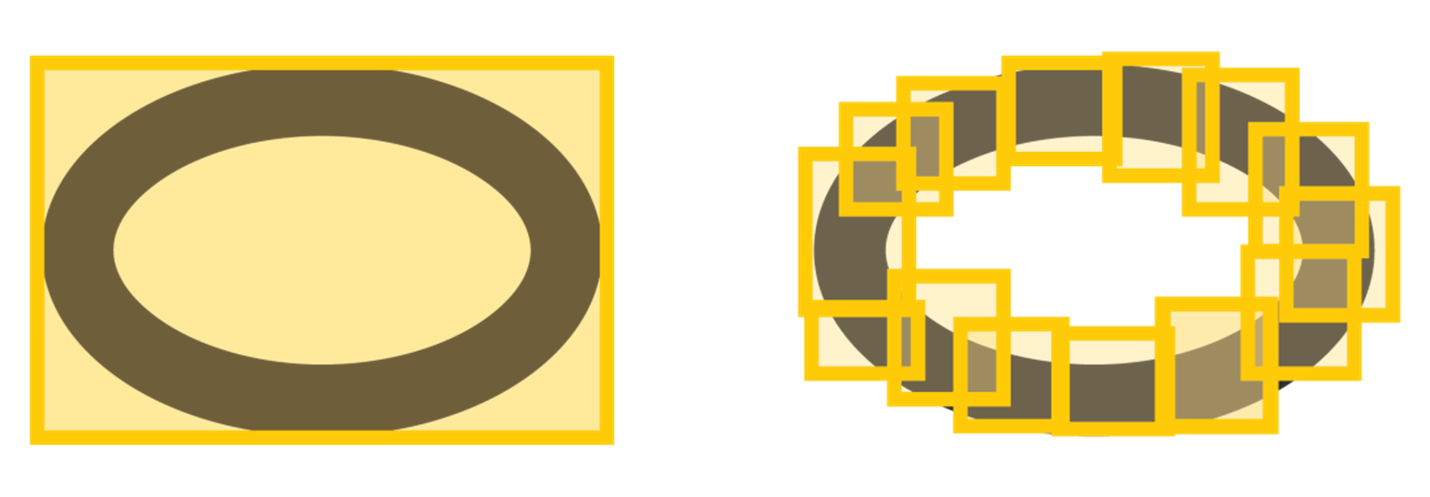
Figure 5. Using multiple AABBs to specify a procedural object can greatly improve ray-tracing performance by minimizing shader invocations in void areas.
In the above example, the 14 AABBs on the right will be more efficient than the single AABB on the left, because rays passing through the center of the torus will not generate any intersection shader invocations. This cost saving can easily outweigh the additional cycles spent in the traversal hardware, as long as a moderate number of AABBs are used.
A similar principle applies to alpha-tested geometry implemented using textured triangles and any-hit shaders. If the texture is known to contain large, transparent regions, then the geometry should be subdivided so that it tightly bounds the non-transparent region. This is also a good content creation practice for rasterization, but it is especially important for ray tracing, due to the comparatively high cost of any-hit shaders.
Be Mindful of Spatial Splits
The BVH is the de facto standard for ray tracing acceleration structures. In a classical BVH, every primitive is placed in exactly one leaf, which guarantees that a given ray traversal will test a given primitive once, at most. In a classical BVH, duplicate any-hit shader invocations can never occur by construction.
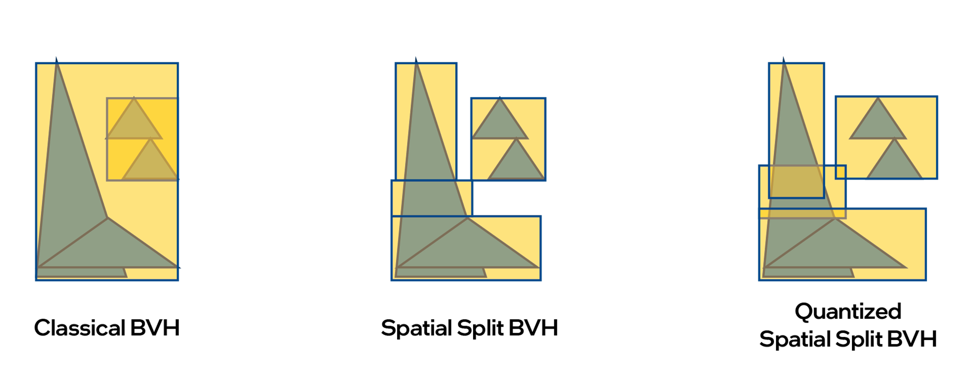
Figure 6. Three scenarios for eliminating void areas in spatial splits in bounding volume hierarchies (BVHs).
Modern ray-tracing engines support spatial splits in BVH, where multiple AABBs are used to tightly bound large primitives. This technique eliminates void areas from the spatial data structure, resulting in fewer node traversals. This can yield double-digit performance gains for ray traversal, but it also introduces the possibility of duplicate intersection tests. If the BVH stores AABBs in a quantized form, this can introduce overlap between the spatial splits, which can result in duplicate any-hit shader invocations for the same primitive. Figure 6 illustrates these three scenarios.
The NO_DUPLICATE_ANYHIT_SHADERS flag requires the implementation to guarantee that an any-hit shader will be invoked only once per-ray for a given primitive. In order to provide this guarantee, it may be necessary to disable spatial splits for all primitives which bear the flag. This can seriously degrade ray-tracing performance, and should be avoided unless absolutely necessary.
Be Mindful of Geometry Compression
While not currently supported on Intel’s Xe-HPG ray-tracing hardware, lossless geometry compression in the RTAS may be supported by future ray-tracing implementations. The guidelines in the DXR spec are generally applicable, and should be followed. Some additional guidelines are listed below:
- Lossless compression might be disabled for “updatable” RTAS to remove its impact on BVH refit performance. Therefore, updatable BVHs are likely to consume more memory and be slower to trace, even if no updates are ever performed. Do not make RTAS updatable unless necessary.
- Lossless compression might be disabled for FAST_BUILD ray flags to improve build performance. We recommend using PREFER_FAST_TRACE for static geometry.
- Lossless compression may be deferred until the RTAS is compacted. Always compact static RTAS.
- Compressed vertex formats such as float16 and snorm may make lossless compression more effective, and reduce memory footprint. However, per-geo transforms will always be applied at full precision, so use of the per-geo transform may erase any benefit from compressed vertices.
General Shader Optimization Guidelines
This section provides authoring guidelines for ray-tracing shaders.
Create Space for Compiler Optimization
- Always use as many ray flags as possible. Ray flags communicate information which the compiler can exploit. If you know that all your instances are already opaque, it is still worthwhile to use RAY_FLAG_FORCE_OPAQUE. Avoid passing ray flags via constant buffers. Use compile-time constants instead, so the compiler can see them.
- Never include a shader in an RTPSO that will not be used by a particular dispatch.
- Use separate RTPSOs for separate ray-tracing passes (shadows, Ambient Occlusion [AO], reflections, etc.). Remember that the compiler has no visibility into which shaders are used in which shader-records. Combining all possible shaders into a single “uber-PSO” forces the compiler to assume that all of them might be used at once, even if the app knows that this is not the case.
- If you do not use ray recursion, set the recursion depth to 1. Set maximum payload size and hit shader attribute counts as low as possible.
- If possible, use only one TraceRay() call per shader.
- Use only one ray-generation shader per RTPSO, ideally with only one TraceRay() call. This allows the compiler to see what the calling code will be doing during hit shader compilation, and optimize accordingly.
- Immutable PSOs provide considerably more optimization flexibility for the driver and compiler, because all shaders are visible to the compiler at the same time. RT-PSOs should be immutable whenever practical.
Be mindful of Intel RTRT’s TSU-based implementation by considering the following:
struct MyRayPayload
{
	uint material_index;
	uint geometry_index;
	float2 barycentrics;
	uint prim_index;
};


RWTexture2D<float3> render_target;

struct LocalRootArguments
{
	uint material_index;
	uint geometry_index;
};

ConstantBuffer<LocalRootArguments> local_arguments;
Texture2D all_my_textures[];
StructuredBuffer<float2> all_my_uvs[];
StructuredBuffer<uint3> all_my_index_buffers[];
sampler all_my_samplers[];
RWTexture2D<float3> render_target;


[shader("closesthit")]
void chs_main( inout MyRayPayload pl, BuiltInTriangleIntersectionAttributes hit_attributes )
{
	pl.material_index = local_arguments.material_index;
	pl.geometry_index = local_arguments.geometry_index;
	pl.barycentrics = hit_attributes.barycentrics;
	pl.prim_index = PrimitiveIndex();
}

[shader("raygeneration")]
void main( )
{
	MyRayPayload pl;
	TraceRay( ... pl );

	// BAD: Resource operations use non-uniform descriptor indices
	uint3 indices = all_my_index_buffers[pl.geometry_index][3*pl.prim_index];
	float2 uv0 = all_my_uvs[pl.geometry_index][indices.x];
	float2 uv1 = all_my_uvs[pl.geometry_index][indices.y];
	float2 uv2 = all_my_uvs[pl.geometry_index][indices.z];
	float2 bary = pl.barycentrics.xy;
	float2 interpolated_uv = uv0*bary.x + uv1*bary.y + uv2*(1-bary.x-bary.y);

	float3 color = all_my_textures[pl.material_id].Sample( all_my_samplers[pl.material_id], interpolated_uv );

	render_target.Store( DispatchRaysIndex().xy, color );
}
The following code sample shows the proper implementation, which minimizes communication and exploits the fact that local root arguments are wave-uniform on Intel® Xe-HPG Architecture.
struct MyRayPayload
{
	// no payload necessary
};


RWTexture2D<float3> render_target;

// these resources are bound to the shader using
// local root buffers or descriptor tables
StructuredBuffer<float2> local_geometry_uvs;
StructuredBuffer<uint3> local_index_buffer;
Texture2D local_texture;
sampler local_sampler;


[shader("closesthit")]
void chs_main( inout MyRayPayload pl, BuiltInTriangleIntersectionAttributes hit_attributes )
{
	// GOOD: Resource operations use uniform descriptors
	uint3 indices = local_index_buffer[PrimitiveIndex()];
	float2 uv0 = local_geometry_uvs[indices.x];
	float2 uv1 = local_geometry_uvs[indices.y];
	float2 uv2 = local_geometry_uvs[indices.z];
	float2 bary = hit_attributes.barycentrics.xy;
	float2 interpolated_uv = uv0*bary.x + uv1*bary.y + uv2*(1-bary.x-bary.y);

	float3 color = local_texture.Sample( local_sampler, interpolated_uv );
	render_target.Store( DispatchRaysIndex().xy, color );
}


[shader("raygeneration")]
void main( )
{
	MyRayPayload pl;
	TraceRay( ... pl );
}
- Avoid spills at re-packing points by minimizing live values across trace calls. If possible, make all TraceRay() calls tail recursive.
- Minimize redundant shader invocations. Use ray flags liberally. If you can eliminate a shader stage then do so. There is a substantial cost for executing a shader even if that shader is empty.
- Pass ray payloads by reference to TraceRay() instead of copying them. Copying payload data may introduce a spill if a TraceRay() or CallShader() occurs.
- Use callable shaders for compute tasks which exhibit high SIMD divergence. This will give the TSU a chance to repack shaders for improved SIMD coherence.
- In Intel RTRT’s implementation, ray payload structures are stored in memory. Reads and writes to ray payloads compile to memory loads and stores. To conserve cache footprint, and minimize memory transfers, applications should do the following:
- Keep ray payloads as small as possible. It is worthwhile to store ray payload data in low-precision formats such as unorm or snorm, using ALU instructions to convert back and forth.
- Remove unnecessary fields from ray payloads. Do not put things in the ray payload that you can get from other places, such as ray data or global constants.
- Do not initialize ray payloads before tracing unless downstream shaders depend on it (and avoid depending on it).
- Prefer recompute to save-and-restore. It is generally better to do work in hit shaders than to store data in payloads and pass back up.
- Avoid redundant payload updates.
Any-Hit Shaders
- Avoid any-hit shaders as much as possible. Added cost for triangles is very high in extra shader launches and memory traffic. If you already have an intersection shader, the added cost is not as high, but still non-zero.
- Use opaque flags aggressively to avoid shader-record access during traversal. If there is no opaque flag used, there will always be a performance penalty, even if the shader record specifies a null any-hit shader.
- Do not use any-hit shaders for intersection filtering by ray type. Instead, use instance masking and ray flags whenever possible. Any-hit shaders should only be used when there are no reasonable alternatives.
- Make your any-hit shaders robust to redundant invocations. Do not use the NO_DUPLICATE_ANY_HIT_SHADERS flag. See the section on spatial splits to understand why.
- Avoid executing any-hit shaders. For alpha-tested geometry, ensure that the base triangles tightly enclose the non-transparent areas. In general, the performance penalty is larger for an additional shader invocation than for a few additional triangles.
Intersection Shaders
- These are expensive for the same reasons as any-hit shaders. Avoid them as much as possible.
- Remember that implementations are allowed to invoke intersection shaders multiple times. Be robust to duplicate invocations.
- Do not use intersection shaders for ray/polygon intersection. Tessellate into triangles and use hardware instead. Do not use intersection shaders if triangles with any-hit shaders can accomplish the same task.
- Do not traverse spatial data structures in intersection shaders. Generate leaf-node AABBs and let the hardware do this for you.
- Be generous with AABBs. A large cloud of AABBs with tight, non-overlapping bounds is better than fewer AABBs with large void areas around the procedural surface. See the section on void areas for more details.
- Early-out of intersection shaders whenever possible. If it is not necessary to enumerate every intersection (e.g., for alpha testing) then don’t do it.
DXR1.1 and RayQueries
DXR1.1 and RayQueries expose a lower-level abstraction to ray tracing, and allow ray tracing from all shader stages. As expected, a lower-level abstraction pushes more responsibility to the developer.
DXR1.1 and RayQueries are fully supported on Intel GPUs from Intel® Arc™ GPU onwards. However, on Intel® hardware, they come at the cost of disabling the use of the TSU to generate coherent shading requests, as RayQueries implement a synchronous form of ray tracing. As a result, RayQueries don't fully leverage Intel’s ray-tracing hardware which has been designed with asynchronous ray tracing in mind.
Above, this guide describes how the TSU 'sorts’ the execution of hit shaders to make sure that all SIMD lanes of the XVE, that run the hit shaders, run the same code, and access the same material resources. (See Understanding the Thread Sorting Unit)
As a reminder, the main reasons for poor XVE/SIMD utilization in ray-tracing workloads are as follows:
- Divergent ray traversal duration/steps for rays, which cause all SIMD lanes of a wave to be blocked until the longest ray traversal path is done.
This is depicted on the right-hand side of Figure 7. It shows how RayQueries stall the execution on all lanes until the longest ray is done. In the same throw, RayQueries also stalls the thread of execution which executes the current wave. This thread is not available to execute other asynchronous work anymore, as depicted on the left-hand side of Figure 7.
As shown in Figure 8, Intel Arc GPUs can avoid all these issues by using DXR1.0 and hit shaders.
- As rays hit geometry, they trigger the execution of divergent shader code paths. Therefore, the lanes of a SIMD wave may need to execute different hit/material shaders. This can mean that all shader paths need to be executed sequentially
Here it falls to the developer to write rendering/compute passes that sort ray hits by execution path to make sure hits can be processed efficiently by the SIMD engines of modern GPUs.
These sorting passes add complexity and reduce the time budget the GPU can spend tracing rays in each frame.
Intel Arc GPUs can typically skip these sorting passes if DXR1.0 is used and the TSU can sort shader code execution. - Because rays hit geometry with divergent materials, SIMD lanes may need to fetch from diverging resources to satisfy shading requests.
Again, to work around this issue developers need to add sorting passes. Intel Arc GPUs can typically skip these sorting passes if DXR1.0 is used and the TSU can manage requests.
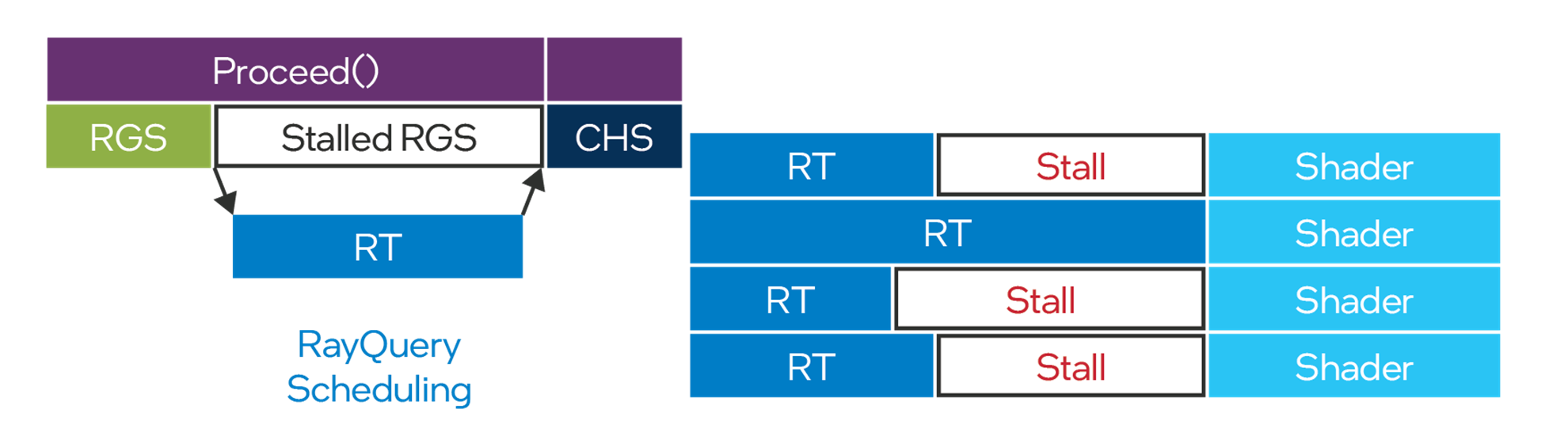
Figure 7. RayQueries can stall execution in many places.
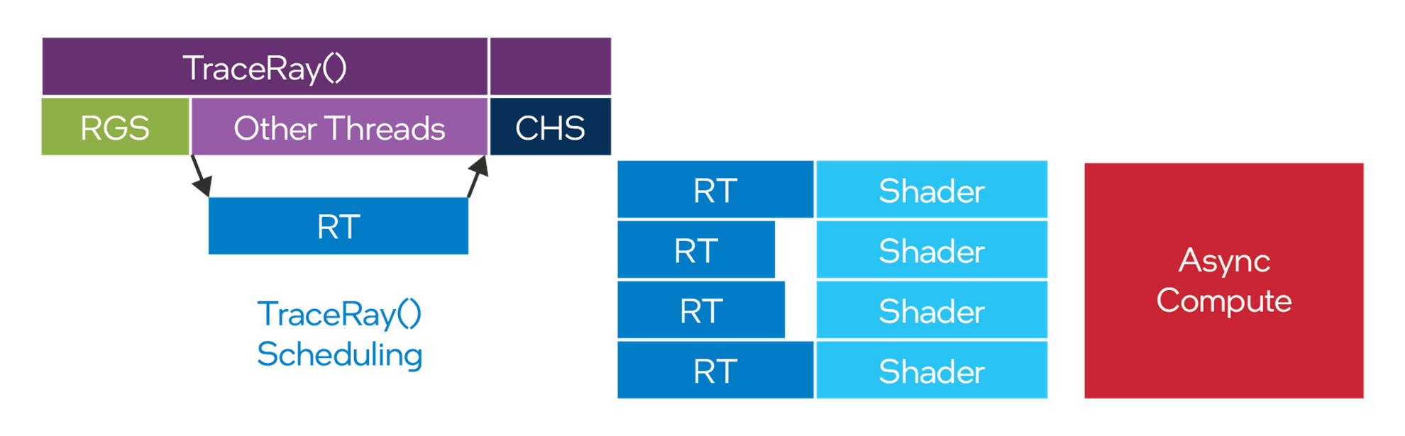
Figure 8. DXR1.0 shaders benefit from Intel® Arc™ GPUs asynchronous ray-tracing architecture
Shaders that use RayQueries need to be implemented with care, especially in compute shaders:
- On Intel architecture, groupshared memory is allocated out of the same L1 cache which services the RTU. As a result, use of groupshared memory in a kernel can degrade ray-tracing performance. This can occur even if the groupshared memory is running on a different queue (e.g. an Async compute queue).
- For best results, compute shaders that use ray queries should avoid using groupshared memory, and the application should avoid scheduling groupshared-intensive work concurrently with other kernels that use ray tracing.
- If you cannot avoid using groupshared memory and ray-tracing together, be careful with barriers in multi-wave workgroups.
- Try to avoid barriers straight after issuing ray queries.
- A barrier may force all waves to wait for the longest ray in all waves.
- Try to keep data within a wave as long as possible.
- Inside a wave, use wave intrinsics instead of barriers.
Refer to the code sample below to review a shader snippet that can result in all waves waiting for the longest ray in a workgroup, which isn’t optimal.
groupshared float RayResults[N_RESULTS];

[numthreads(N_WAVES*WAVE_SIZE, 1, 1)]
main(...)
{
	ZeroRayResults(); // set RayResults to 0.0f
	while( GetRaysForCurrentWave(...) )
	{
		RayQuery<...> rq;
		rq.TraceRayInline(gRtScene, 0, 0xff, Rays[lane]);
		rq.Proceed();
		GroupMemoryBarrierWithGroupSync();

		if(rq.CommittedStatus()==COMMITTED_NOTHING)
			RayResults[GetRayResultsIndex()] += 1.0f;
	}

	// iterate over RayResults to compute final result
	...
}
The following code sample is a better example, showing a good multi-wave workgroup.
groupshared float RayResults[N_WAVES][N_RESULTS];

[numthreads(N_WAVES*WAVE_SIZE, 1, 1)]
main(...)
{
	float LocalRayResults[N_RESULTS] = {0.0f};
	ZeroRayResults(); // set RayResults to 0.0f

	while( GetRaysForCurrentWave(...) )
	{
		RayQuery<...> rq;
		rq.TraceRayInline(gRtScene, 0, 0xff, Rays[lane]));
		rq.Proceed();

		if(rq.CommittedStatus()==COMMITTED_NOTHING)
			LocalRayResults[GetRayResultsIndex()] += 1.0f;
	}

	// use wave intrinsics to combine results from waves

	if(WaveIsFirstLane() )
	{
		for( int i = 0; i < N_RESULTS; ++i )
			RayResults[current_wave][i] = WaveActiveSum(LocalRayResults[i]);
	}

	GroupMemoryBarrierWithGroupSync();

	// iterate over RayResults to compute final result
	...
}
Conclusion
Real-time ray tracing was once considered too resource-intensive for real-time performance, but the technology continues to gain acceptance. Developers seeking to add realism and build immersive qualities into their projects should consider the benefits of learning this technology as it grows in importance. This guide joins a growing suite of tools, APIs, specifications, and guidelines to help in that effort.