Introduction
Persistent memory (PMEM) technology is set to revolutionize the world of in-memory computing by bringing massive amounts (up to 6 terabytes (TB) per two-socket system) of byte-addressable non-volatile memory (NVM) at speeds close to those of dynamic random access memory (DRAM) for a fraction of DRAM’s cost. The most impactful benefits for in-memory computing include reduced application start-up time (no need to recreate memory data structures) and increased memory capacity. Given these developments, the question arises as to whether high-performance computing (HPC) can also take advantage of PMEM technology.
This article addresses this question by dividing the potential space of impact into three areas: system, middleware, and application. It provides general information, potential architectural source code changes, and real-world application examples for each area. This article doesn’t cover every possible case, and since this is a new technology, the examples shown here are still a work in progress.
Overview of Persistent Memory (PMEM) Technology
PMEM in Perspective
PMEM technology can be thought of as the latest evolution in the journey of NVM technologies. NVM technologies range from classic magnetic tapes, hard disk drives, and floppy disks, to read-only memory chips and optical disks, to the latest solid state drives (SSDs) in the market today. The common factor among all these technologies has always been the larger capacity but also poorer performance when compared to DRAM. This has, historically, created the two levels of system storage (primary versus secondary) that we are familiar with today.
Primary storage is designed to be very fast in order to feed the CPU with all the “hot” data it needs during computation, while secondary storage is designed for parking “cold” data and programs that are not needed at the moment but that need to survive when power is turned off. Although secondary storage can be used to store “hot” data, and in fact is used as such when DRAM is not large enough (for example, when swapping memory pages to disk), this approach is undesirable due to the non-negligible performance impact. Simply put, primary storage is fast, small, and volatile, while secondary storage is slow, large, and persistent.
With that in mind, we can see why one of the key differences in the design between the two levels is data access granularity. While primary storage allows CPUs to address and randomly access single bytes of data, the unit of data access in secondary storage is usually a block of 4 KB (sometimes even greater). This bulk access to data is needed to compensate for access latencies, which are orders of magnitude larger than those of primary storage. This difference in access granularity between primary and secondary storage is also responsible for the need to create two data models for applications:
- For primary storage, the data model is more complex and richer, such as trees, heaps, linked lists, hash tables, and so on
- For secondary storage, the data model is less flexible, such as serialized data structures in markup languages (for example, XML), comma-separated values files, structured query language tables, and so on
How is PMEM Different?
The revolutionary aspect of PMEM is that it will be byte-addressable and fast (like primary storage) without sacrificing too many of the benefits of secondary storage like large capacity, persistence, and low cost per byte (see Figure 1). Intel® Optane™ memory technology makes all this possible, in addition to providing access latencies close to those of DRAM. PMEM DIMMs will be directly accessible by the CPU, removing intermediate overheads such as the PCIe* bus transfer protocol. Although the world will still need secondary storage to cheaply archive massive amounts of data, PMEM is positioned to be the technology that will allow a large number of applications and systems to unify their data models.
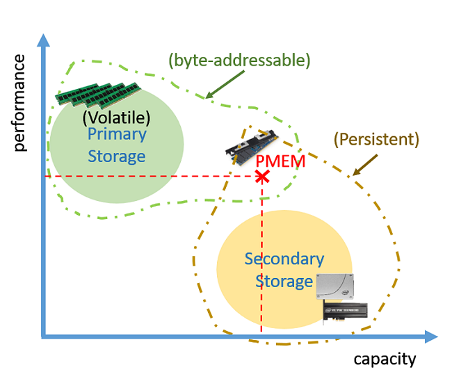
Figure 1. How PMEM technology compares to DRAM and SSDs in terms of performance versus capacity. The figure also shows how PMEM is both byte-addressable and persistent.
An application that wants to persist some data structures on a PMEM device needs to make sure that modifications to that data structure are done atomically (for example, by using transactions) so as to avoid corruption caused by data stored in CPU caches not being flushed on time before power is turned off. However, an application can forgo this part if all it wants is more primary storage capacity. This can come in handy for memory-bound HPC applications, as we will see next.
The System’s Point of View
The first benefit that PMEM will bring to HPC will be a larger primary storage capacity (6 TB per two-socket system). To understand how HPC applications could potentially take advantage of PMEM, first we need to conceptually visualize how this new technology will fit inside the overall memory hierarchy.
Three Logical Architectures
As shown in Figure 2, applications can use three logical architectures when integrating PMEM: DRAM as cache, PMEM as a DRAM extension, and DRAM as a temporary buffer.
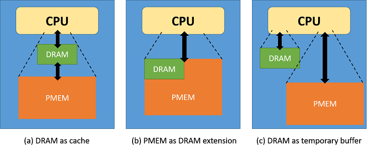
Figure 2. Three logical architectural possibilities for using PMEM as extended capacity for memory-bound applications
In the DRAM as cache scenario (see Figure 2a), applications will use PMEM as a new layer inside the memory hierarchy. Applications will allocate memory for their data structures in PMEM, hence using PMEM as primary storage, while using DRAM only as L4 cache. However, with this approach, all data consumed (that is, addressed) by the CPU during regular computation will still be against DRAM. This means that data movement between DRAM and PMEM will need to be handled using some kind of explicit caching supporting code.
In the PMEM as DRAM extension scenario (see Figure 2b), applications will use all the available memory capacity as a single memory pool. Memory can first be allocated in DRAM; if more is needed, allocation then continues on PMEM. With this approach, data consumed by the CPU during regular computation will be either in DRAM or PMEM, causing variability in access latencies depending on what part of the data the CPU accesses.
In the DRAM as temporary buffer scenario (see Figure 2c), applications composed of different computational kernels, each one using different memory usage patterns, could utilize one type of memory or the other depending on the particulars of each kernel. An example of such a kernel is the 3D Fast Fourier Transform (3D-FFT), which transforms data in order to be used with spectral methods. 3D-FFTs require multiple passes over the same data points, hence it is advantageous to compute it always against DRAM. Note that logical architecture (a) is really a subset of (c).
Stencil Applications
Memory-bound, large-scale HPC applications will directly benefit by being able to allocate larger problem sizes. An example of such applications are stencil (that is, nearest neighbor) computations. Stencil applications are used in the implementation of partial differential equation solvers through iterative finite-differences techniques. Solving the 3D heat equation is a typical stencil problem.
Ht+1 [i,j,k]=a Ht [i,j,k]+b (Ht [i-1,j,k]+Ht [i,j-1,k]+Ht[i,j,k-1]+Ht[i+1,j,k]+Ht [i,j+1,k]+Ht [i,j,k+1])
This equation is a stencil representing a single out-of-place (that is, a new value is stored in Ht+1, not Ht) Jacobi iteration executed for each data point (i,j,k) in a 3D grid. Since this access pattern is regular and predictable—and hence data can be smartly pre-fetched to DRAM before it is used—it is ideal for the DRAM as cache architecture. Indeed, this kind of data pre-fetching is known in the literature as “blocking.” For example, with blocking, data is split into core blocks of equal size that fit neatly into L3 cache, in a way that cache misses can be significantly reduced. Likewise, core blocks can subsequently be split into thread blocks for parallelization or even register blocks to take advantage of data level parallelism (that is, vectorization).
Following this logic, we can think of DRAM blocks—an extra layer of blocking to optimize data pre-fetching to DRAM. Figure 3 shows a high-level description of blocking with the new added layer on the far left.
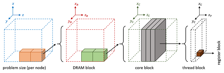
Figure3. Pre-fetching data for stencil applications using blocking with an extra layer (far left) added for PMEM. This figure is a modified version of Figure 2 that appears in Stencil Computation Optimization and Auto-tuning on State-of-the-Art Multicore Architectures.
The Middleware’s Point of View
Another way in which HPC applications can take advantage of PMEM is by enhancing libraries and services sitting at the middleware layer, making them “PMEM-Aware.” The idea is to bring the benefits of this new technology to applications, while also avoiding significant coding efforts.
PMEM-Aware Checkpoint/Restart
Checkpoint/Restart (C/R) in HPC can be enhanced by adding a PMEM-aware buffer at the local node level. These checkpoints can then be transferred asynchronously from PMEM to a remote Distributed File System (DFS) or even to intermediate burst buffer servers, without slowing the progress of execution significantly. This use of C/R is known in the community as hierarchical C/R (see Figure 4).
Persistence assures applications that the last checkpoint done will be readily available as soon as all processes finish check-pointing to PMEM (even before finishing remote copying to the DFS). This is so, of course, as long as the failure in question does not affect the data saved on the PMEM DIMMs. Persistence can also help reduce the frequency of remote check-pointing to DFS. The classic Young’s formula (Tc= √(2 × C ×MTBF)) says that the frequency of check-pointing (1/Tc) is inversely proportional to the mean time between failures (MTBF). Because PMEM adds an extra layer of security to data, the probability of failure decreases, making MTBF increase. Less-frequent remote check-pointing means less overhead overall (transferring huge amounts of data remotely is not cheap).
Although other alternatives exist for doing local checkpoints, such as SSDs, PMEM’s unique features will likely make it the key technology in this regard.
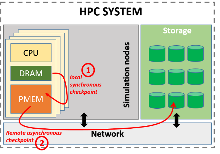
Figure 4. PMEM as a first level in hierarchical check-pointing.
Since PMEM’s capacity will be larger than that of DRAM, it will be possible to store more than one checkpoint at a time if needed. This buffering can help improve network utilization by coordinating remote copying with phases of low application network traffic.
MPI-PMEM Extensions
Probably the most well-known middleware in HPC is the Message Passing Interface (MPI). This section describes two extensions that have already been written for MPICH*: the open source implementation of MPI by Argonne National Laboratories. You can download them in the linked GitHub* repository, and use and modify them. Of course, these extensions aren’t the only ones possible.
The first extension, located under the directory mpi_one_sided_extension, makes MPI one-sided communication PMEM-Aware by allowing processes to declare “persistent windows.” These windows, which outlive the execution of the application, can be useful for C/R. Another use case is parameter sweep scenarios, when the same application needs to be run with the same input data but using different input parameters. For these cases, the input data can be loaded just once from secondary storage to PMEM and then reused for multiple executions, hence reducing application start-up time.
The second extension, located under the directory mpiio_extension2, integrates PMEM into MPI-IO using two modes: (1) PMEM_IO_AWARE_FS and (2) PMEM_IO_DISTRIBUTED_CACHE. In (1), all the available PMEM DIMMs attached to all the nodes are combined into a single logical view to form a PMEM DFS. Requests for data not present in the current node are forwarded to the appropriate one using a broker. In (2), PMEM DIMMs attached to the nodes serve as a huge cache (again, up to 6 TB per two-socket system) for data stored in a remote DFS. If we think again that PMEM will enjoy speeds close to those of DRAM, the potential for mode (2) to boost MPI-IO performance cannot be overlooked.
Persistent Workflow Engines
Another class of HPC middleware used in the scientific community is workflow engines (WEs) such as Galaxy* or Swift*. Jobs that run as workflows must divide the work into individual tasks. These tasks are run independently from one another (they are data-independent so they do not share any state, and all input data is passed by value), and each one is usually an autonomous piece of software. You can think of a WE as the glue that sticks together different software pieces, which by themselves would not talk to each other, to create a coherent whole ─ connecting outputs to inputs, scheduling, allocating needed resources, and so.
One of the main issues with WEs is that, for the most part, tasks talk to each other via files (and sometimes database engines). A task usually runs to perform a specific analysis, for which it reads its input(s) file(s) and writes the results as output file(s), which will be used by other tasks as input(s) and so on. Here we can see how PMEM can be leveraged to create a fast buffer for a workflow’s intermediate data instead of relying so much on files. Tasks can also be optimized to use specific memory data structures directly instead of having to recreate them from flat files, as is usually the case, which can also help simplify code and speed up execution.
The Application’s Point of View
At the application level, the applications themselves are directly responsible for defining what data structures should be permanent and act accordingly (for example by writing to them atomically to avoid potential corruptions). Intel is closely collaborating with other key players in the industry through the Storage and Networking Industry Association (SNIA), which has developed the Persistent Memory Developer Kit (PMDK) based on the NVM Programming Model (NPM) standard. PMDK is composed of multiple open source libraries and APIs, whose goal is to aid programmers in adapting their applications to PMEM. Although its usage is not mandatory, it is nonetheless recommended, especially for newcomers.
In the case of HPC applications, especially simulations, the benefit of persistent data structures is unclear. When we think of access latencies, we need to ask: What is the added benefit of persistence that can make it worth having larger access latencies, plus the overhead of transactions? In addition, given the nature of HPC simulations where data evolves over time, is it worth persisting data that will change soon? Apart from check-pointing, it is difficult to think of other obvious benefits that persistence can bring to HPC simulations. If you think otherwise and have a good use case, please contact me.
However, other applications used in conjunction with HPC simulations can benefit by having persistent data structures. An example of this is with situ visualization.
Interactive In Situ Visualization with PMEM
In situ visualization is a technique designed to avoid excessive data movement between the HPC system, where simulations are run, and the visualization system, where graphics are rendered (see Figure 5). Instead of check-pointing data to a file system to be used later as input for visualization, the visualization itself—or part of it, for visualizations are usually expressed as a sequence of data transformations—is done in the HPC system at the same time as data is being generated by the simulation. A visualization library is called at the end of each time step with raw data passed, in most cases, by reference (to avoid data copying as much as possible). The simulation can continue to the next step only when the visualization is done.
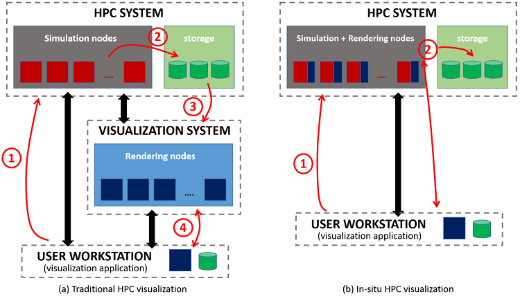
Figure5. (a) Traditional HPC visualization versus (b) in situ. In (a), the simulation performs expensive checkpoints (step 2) to store the raw data for visualization. However, in (b) a large part of the data transformation and rendering, if not all, is performed in the HPC system itself. Transformed and/or rendered data, which is smaller than raw data, is then forwarded to the visualization application or stored for later use.
One of the limitations of this approach is lack of flexibility. Once the simulation advances to the next time step, data from the previous one is usually overwritten in memory, which limits the opportunities to interact with the visualization, such as changing parameter values for coloring, adding or removing filters, slicing, adding extra lights, moving the camera, and so on. In addition, restarting a simulation, which may have been running for days, to change some visualization parameters is not feasible either.
Here is where PMEM can help by allowing the persistence of a window of time steps. This window, in turn, can allow simulation interaction by changing parameters and re-rendering the simulation from the beginning of the window. One can imagine a scenario where users, dissatisfied with the visualization that is currently being generated, may want to explore the use of different visualization options and parameters before continuing with the simulation, but without restarting it. Since the window is persistent, it outlives the simulation. The visualization could, theoretically, be accessed and interacted with long after the simulation is done.
Summary
This article explored the idea of enhancing HPC with PMEM technology. Starting with a general definition of PMEM, the article then described the potential impact to the system, middleware, and application, as well as potential architectural code changes and real-world application examples about each area. All the examples shown in the article are still works in progress and subject to changes over time. I welcome any new ideas and developments from the community. Email me at eduardo.berrocal@intel.com.
About the Author
Eduardo Berrocal joined Intel as a cloud software engineer in July 2017 after receiving his PhD in Computer Science from Illinois Institute of Technology (IIT) in Chicago, Illinois. His doctoral research interests focused on data analytics and fault tolerance for HPC. In the past he worked as a summer intern at Bell Labs (Nokia), as a research aide at Argonne National Laboratory, as a scientific programmer and web developer at the University of Chicago, and as an intern in the CESVIMA laboratory in Spain.
Resources
- Stencil Computation Optimization and Auto-tuning on State-of-the-Art Multicore Architectures, Kaushik Datta et al., http://mc.stanford.edu/cgi-bin/images/e/ec/SC08_stencil_autotuning.pdf.
- Link to MPI-PMEM Extensions code in GitHub.
- The Persistent Memory Developer Kit (PMDK).
- The Non-Volatile Memory Programing (NMP) Standard: https://www.snia.org/tech_activities/standards/curr_standards/npm.
- The Open Source, multi-platform data analysis and visualization application ParaView: https://www.paraview.org/.
- In-Situ Visualization: State-of-the-art and Some Use Cases, Marzia Rivi et al., CINECA & Scientific Computing Laboratory, Institute of Physics Belgrade, University of Belgrade, http://www.prace-ri.eu/IMG/pdf/In-situ_Visualization_State-of-the-art_and_Some_Use_Cases-2.pdf.
- The Message Passing Interface (MPI).
- A User-Level InfiniBand-Based File System and Checkpoint Strategy for Burst Buffers, Kento Sato et al., 2014 14th IEEE/ACM International Symposium on Cluster, Cloud and Grid Computing (CCGrid), http://ieeexplore.ieee.org/abstract/document/6846437/.
- MPICH: a high performance and widely portable implementation of the Message Passing Interface (MPI) standard, http://www.mpich.org.
- Galaxy Workflow Engine Project: https://galaxyproject.org/.
- Swift Workflow Tool: http://swift-lang.org/main/.
- Optimization of a multilevel checkpoint model with uncertain execution scales, Sheng Di et al., Proceedings of the International Conference for High Performance Computing, Networking, Storage and Analysis (SC’14), 2014, https://dl.acm.org/citation.cfm?id=2683692.