Introduction
Configuring redundancy in storage solutions is a popular way to improve overall system performance, fault tolerance, or both. Redundancy usually takes the form—at the single server level—of a Redundant Array of Independent Disks (RAID), which is implemented either in software or using specialized hardware controllers. The primary levels of RAID are 0, 1, and 4/5/6. RAID 0 can be striped or linear/concatenated, RAID 1 mirrors data and RAID 5 (as well as 4 and 6) add parity to a RAID 0 striped for fault tolerance. I will not go into other—less popular—RAID levels used out there, although worth mentioning is RAID 10, which combines RAID 1 and 0 (striped between groups, mirrored inside groups).
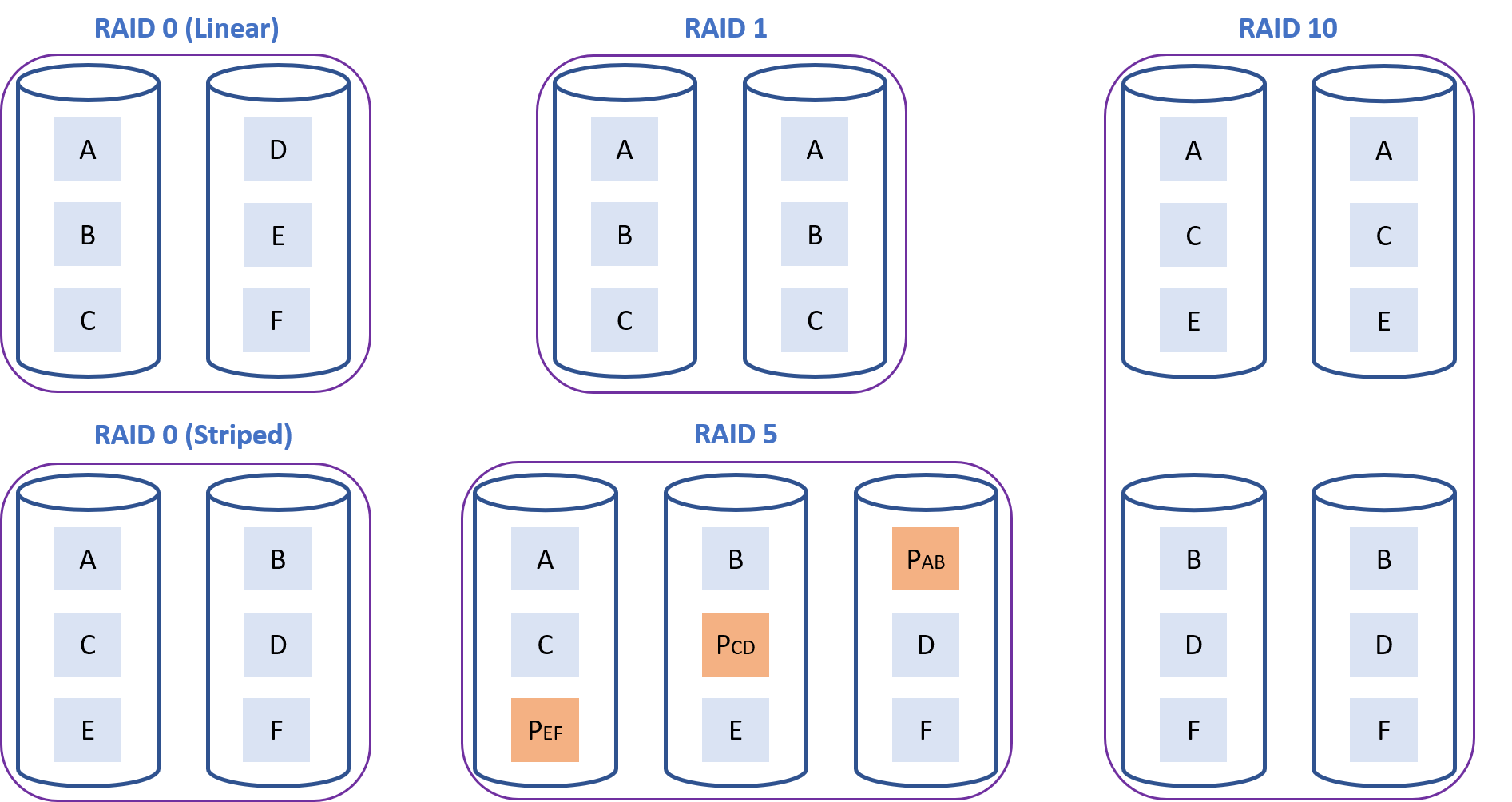
Figure 1. Primary levels of RAID.
This article will explore RAID possibilities for Intel® Optane™ persistent memory (PMem) modules and discuss situations where it is desirable to use RAID on top Intel Optane PMem modules. The RAID configurations tested are 0 (linear and striped), 1, and 5.
This article represents a natural continuation of my previous article Speeding Up I/O Workloads with Intel® Optane™ Persistent Memory Modules, whose reading I recommend before diving into this one.
A basic understanding of persistent memory concepts and terminology is assumed. If you are entirely new to persistent memory, please visit our page on Intel® Developer Zone, where you will find the information you need to get started.
Intel® VROC and Optane™ Persistent Memory Modules
Intel® Optane™ persistent memory (PMem) modules connect directly to the CPU’s memory controller. Given that the memory controller does not support RAID configurations, hardware RAID is not supported for Intel® Optane™ PMem modules. Intel® Virtual RAID on CPU (Intel® VROC), a RAID solution implemented for Intel® Xeon® Scalable processors, cannot be used in this case either. Intel® VROC works with a new feature called Intel® Volume Management Device (Intel® VDM), an integrated controller inside the CPU PCIe root complex. Because of this, Intel® VROC only works with PCIe devices.
Striping across all memory channels within a single CPU socket—what we call interleaving—is, of course, supported (it is memory after all), and is equivalent to RAID 0. Striping (interleaving) across CPU sockets is not supported. Intel® Optane™ PMem modules can also be configured as non-interleaved, which means that other RAID configurations are possible at the software level.
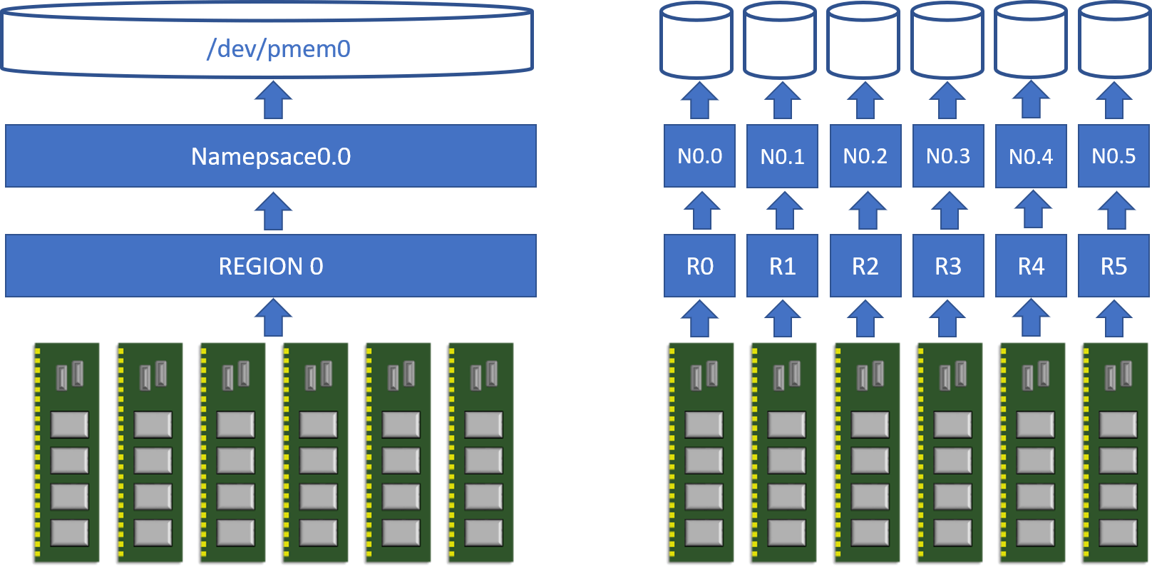
Figure 2. Interleaved (left) versus non-interleaved (right) configurations for Intel Optane PMem modules in app-direct mode within one CPU socket. Multiple namespaces can be created per region too (not shown here for simplicity).
Direct Access (DAX) – Bypassing the File System
For those of you who are new to the world of PMem, Direct Access (DAX) is a mechanism that allows applications to directly access PMem media from user space bypassing the traditional I/O stack (page cache and block layer). DAX avoids costly context-switches to the operating system (OS), and it is the fastest possible path to the persistent media (essential to take advantage of PMem’s extremely low latencies). DAX works through memory mapping, where memory-mapped files residing in PMem are accessed through CPU loads and stores without the need for the OS to copy the data to DRAM first. File systems supporting DAX include EXT4 and XFS in Linux and NTFS in Windows. Having the possibility to use DAX for our I/O workloads is interesting, especially for small and random I/O operations.
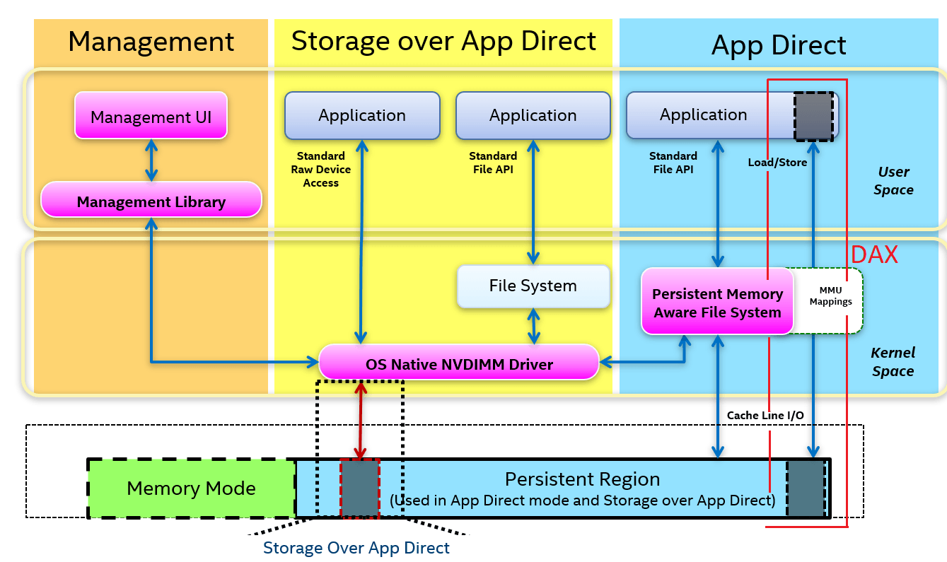
Figure 3. NVM Programming Model (NPM) standard, developed by key players in the industry through the Storage and Networking Industry Association (SNIA). DAX is shown to the right.
Unfortunately, DAX is only supported for RAID 0 configurations. Parity computations (required for RAID 4, 5, and 6) and mirroring (required for RAID 1 and 10) are done within the block layer at the OS level and at block size granularity. A context-switch to the OS is necessary to perform these operations. In contrast, RAID 0 uses simple address translation from virtual to physical block location (device + offset), which, in the case of PMem devices, corresponds to a translation from virtual blocks to memory addresses.
Redundancy with Two Sockets
RAID 0
I will start my experiments by looking at RAID 0 configurations in multi-socket environments. Some developers are curious about this because they are trying to avoid code modifications that go along with making an application Non-Uniform Memory Access (NUMA)-aware. Seeing all the system’s persistent memory capacity as one big continuous chunk makes programming software less complex.
For all the experiments shown in this article, I will use a 2-socket server with 12 DRAM DIMMs and 12 Intel® Optane™ PMem modules. This hardware configuration maximizes the available bandwidth in the system. All tests are done using version 3.20 of the Flexible I/O (FIO) tool (more details are presented in Appendix A), and the XFS file system (see Appendix B). Software RAID volumes are created using the Linux Logical Volume Manager. See Appendix C for details about how the volumes are created. For more information regarding the testing platform, see the performance disclaimer at the end of this article.
The first experiment, shown in Figure 4, compares software RAID 0 striped and linear to NUMA-aware workloads. RAID 0 configurations were created using two namespaces, each corresponding to one socket (each socket having six interleaved modules). In the case of the NUMA-aware workloads, both namespaces—/dev/pmem0 and /dev/pmem1—are used directly. The threads accessing a namespace in a particular socket are always pinned to that socket.
All workloads in this experiment had DAX enabled. I/O against DAX means that applications that rely on write atomicity at the block/sector level can get their data corrupted by torn blocks/sectors in the event of a crash or power failure (x86 architecture only guarantees to write atomically 8 bytes at a time during memory copies). The lack of block write atomicity doesn’t affect the file system’s metadata (the file system takes care of that). For a more extended discussion about this topic, and to see some performance numbers, please read my previous article Speeding Up I/O Workloads with Intel® Optane™ Persistent Memory Modules.
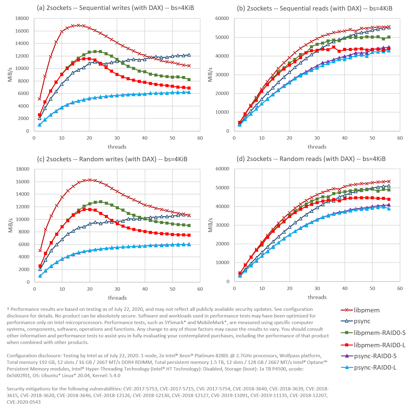
Figure 4. Using FIO, we compared a software striped (S) and linear (L) RAID 0 against a NUMA-aware configuration in a 2-socket environment for (a) sequential writes, (b) sequential reads, (c) random writes, and (d) random reads. The file system (XFS) is DAX enabled; read size (block size in FIO) in 4KiB.
The first observation from Figure 4 is that the FIO engine libpmem (one of the main libraries of the Persistent Memory Development Kit), represented in dark red, green, and light red, always performs better than the NUMA-aware psync (dark blue) for low thread counts, even when libpmem is running on top of RAID 0 (green and light red). In this particular case, bypassing the file system is more important for performance than being NUMA-aware. However, the NUMA-aware psync can continue scaling at higher thread counts as others flatten out or decrease, making it more attractive. Nonetheless, it still cannot reach the peak bandwidth for sequential writes achieved by libpmem on RAID 0 striped, or the peak bandwidths for random writes conducted by libpmem running on both RAID 0 striped and linear.
The absolute winner is, not surprisingly, the NUMA-aware libpmem (dark red), while the worst performers are the psync engines running on both RAID 0 striped and linear (purple and light blue). However, the performance is decent for the latter—particularly for reads—making RAID 0 over two sockets a viable solution to speed up I/O workloads using traditional read/write calls.
The second observation is that the NUMA-aware workloads (dark red and dark blue) always perform better than their engine-equivalent running on top of RAID 0. We can get some data to visualize why. For example, we can look at the percentage of memory requests that are handled locally versus remotely. We can also look at the traffic flow through the Intel® Ultra Path Interconnect (UPI) link. The Intel® UPI link is the socket-to-socket interconnect for Intel® Xeon® Scalable Processors. We can use tools like Intel® Vtune™ Profiler – Platform Profiler to visualize NUMA related information. As an example, consider the case for sequential reads from 30 threads presented in Figure 5, where the NUMA-optimized run for engine psync (41.7 GiB/s) is compared against psync running on linear RAID 0 (32.9 GiB/s):

Figure 5. NUMA access data from Intel® Vtune™ Profiler – Platform Profiler comparing the same FIO run (sequential reads from 30 threads using the psync engine) under two different configurations for Intel® Optane™ PMem modules: (1) NUMA-aware—labeled “psync”—and (2) NUMA-oblivious running on top of a linear RAID 0—labeled “psync-RAID0-L”.
As it is possible to see in Figure 5, almost half of the memory accesses are going to the opposite socket for the RAID 0 configuration, and the UPI throughput generated is 22.88 GB/s on average. These results are somewhat expected given the nature of the workload, i.e., data is distributed between the two sockets and threads chose files at random. We can expect approximately 75% of accesses to be remote in a 4-socket system with a similar workload.
The third and final observation is that linear RAID 0 performs worse than striped RAID 0 for the engine libpmem (light red worse than green) at high thread count. This phenomenon is simply a byproduct of the distribution of data within the linear RAID 0. Data in a striped RAID 0 is always evenly distributed, while a linear RAID 0 is only evenly distributed when 100% full. All the experiments presented in this article always use around 80-85% of the available space. For linear RAID 0, this translates into having socket 0 at 100% capacity and socket 1 at 60-70%. Uneven distribution of data means an uneven distribution of I/O accesses, which affects performance when going beyond the saturation point. We can visualize this with Platform Profiler and look at the number of write operations received by each socket. As an example, consider the case for sequential writes from 30 threads presented in Figure 6, where engine libpmem running on striped RAID 0 (11.2 GiB/s) is compared against libpmem running on linear RAID 0 (8.85 GiB/s):
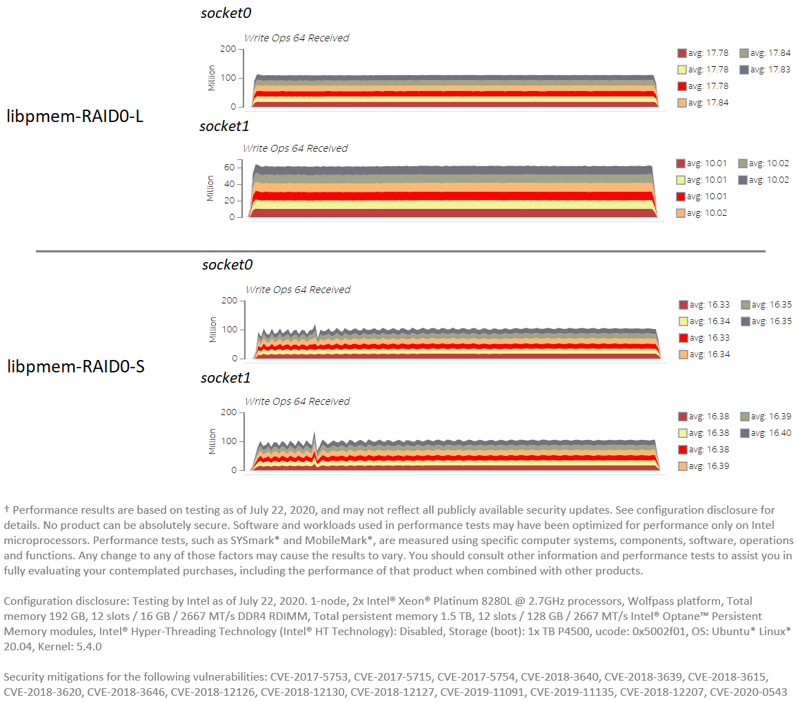
Figure 6. PMem traffic data from Platform Profiler comparing the same FIO run (sequential writes from 30 threads using the libpmem engine) under two different configurations for RAID 0: (top) linear RAID 0, and (bottom) striped RAID 0.
We can see in Figure 6 how the average traffic per module is different between the two sockets for the linear RAID 0 case. While modules in socket 0 get an average of 17.8 million operations per second, modules in socket 1 get 10.01 million. Meanwhile, the traffic generated is evenly distributed for the striped RAID 0 case: around 16.35 million operations per second per module for both sockets.
RAID 1
The next experiment shows performance results for RAID 1. One namespace is created per socket (each socket having six interleaved modules), so the RAID 1 is duplicating the data at the socket level using one namespace to mirror the other.
Given that DAX is not supported for RAID 1, only the psync engine is tested. Likewise, the page cache is bypassed using the FIO option direct=1, which opens all files with the O_DIRECT flag. Bypassing the cache is needed to have meaningful results in the case of reads. Because the size of Intel® Optane™ PMem is limited, the same files are re-utilized repeatedly by all the threads during the duration of the tests. If the page cache is used, there is a high chance that a file is already cached before reads are even issued, getting unrealistic read performance between 100-120 GiB/s. Since we are not interested in caching effectiveness in FIO tests, the page cache is bypassed.
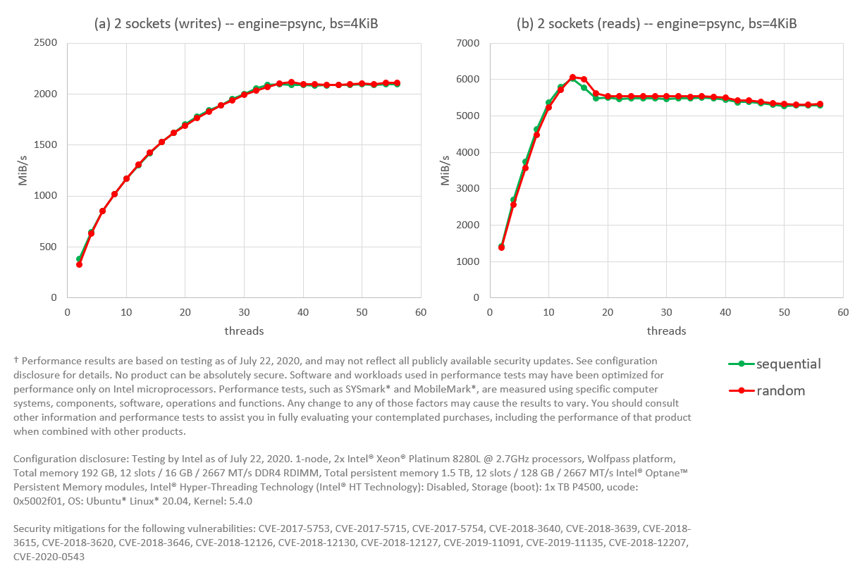
Figure 7. FIO with the psync engine. Intel® Optane™ PMem modules configured as RAID 1 with one namespace per socket. Tests for writes are presented in (a), while reads are shown in (b).
As figure 7 shows, sequential and random workloads perform almost the same. Writes top at around 2 GiB/s, while reads top at 5.9 GiB/s for 12 threads and then stay at around 5.5 GiB/s for higher thread counts. To put these numbers is perspective (see Figure 4), writes top above 6 GiB/s for psync on RAID 0 and above 10 GiB/s for the NUMA-aware psync. Moreover, reads top above 40 GiB/s for psync running on RAID 0 and above 50 GiB/s for the NUMA-aware psync.
Given these unsatisfactory performance numbers, software RAID 1 configurations over two sockets are not recommended for Intel® Optane™ PMem modules. At least not until the code for software RAID 1 undergoes optimizations aimed for PMem devices. Other forms of fault tolerance should be implemented to account for module failure (see section Fault Tolerance with Persistent Memory below).
RAID 5
Next in line is RAID 5. In this case, Intel® Optane™ PMem modules are configured as non-interleaved, which means that a single namespace is created per module. Since there are twelve modules in the system, we have twelve namespaces. As in the case of RAID 1, the page cache is bypassed with the FIO option direct=1.
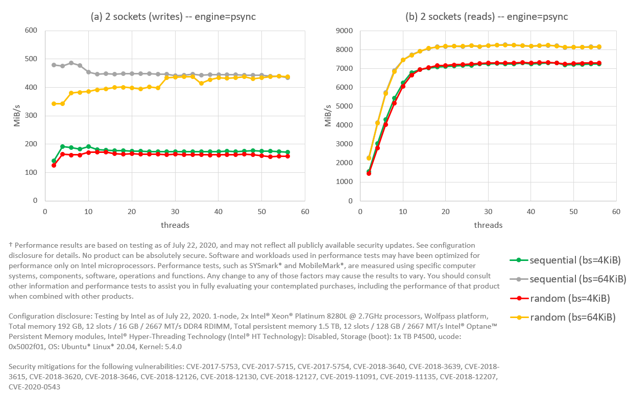
Figure 8. FIO with psync engine. Intel® Optane™ PMem modules configured as RAID 5 (stripe=4KiB), with 12 modules across two sockets; read sizes (block size in FIO) tested are 4KiB and 64KiB. Tests for writes are presented in (a), while reads are shown in (b).
With RAID 5, we get a huge penalization for writes: performance stays between 150-200 MiB/s for any number of threads. This flat curve suggests a thread contention somewhere in the code path. We can improve performance a little bit by increasing the granularity of writes. For example, by writing 64KiB at a time (bs=64k in FIO), we can increase write performance to around 450 MiB/s, but not beyond that.
Reads top at 7 GiB/s for read size of 4 KiB, and 8 GiB/s for read size of 64 KiB. Read performance is still too slow to compensate for the extremely low write performance. The experiment in Figure 8 is done with a stripe size of 4 KiB. We can improve read performance by increasing the stripe size to 64KiB, as shown in Figure 9:
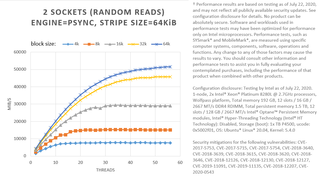
Figure 9. FIO with psync engine; random reads. Different read sizes (block sizes in FIO) tested for Intel® Optane™ PMem modules configured as RAID 5 (stripe=64KiB), with 12 modules across two sockets.
Figure 9 shows that using 64 KiB for both the stripe size and the read size (block size in FIO), we can get performance at high thread counts, comparable with NUMA-aware psync. Increasing the granularity of I/O can help us hide software latencies. If your workload is one such that writes are not common, and reads can be done in large chunks of 64KiB or more, RAID 5 may be a viable solution to protect against a single module’s failure.
However, in general, as in the RAID 1 case, software RAID 5 configurations over two sockets are not recommended for Intel® Optane™ PMem modules.
Redundancy within One Socket
Let’s look now at a single socket. For this experiment, I use the same server used for the two-socket experiments shown above. The only difference is that this time, only Intel® Optane™ PMem modules within one socket (up to six modules) are used. We don’t need to worry about NUMA issues since no I/O crosses sockets.
Only one type of RAID 0 (striped) is tested this time. All levels of RAID are tested using a non-interleaved configuration for Intel® Optane™ PMem modules. With a single namespace per module, that gives us six namespaces in total. RAID 1 uses three namespaces to duplicate the other three.
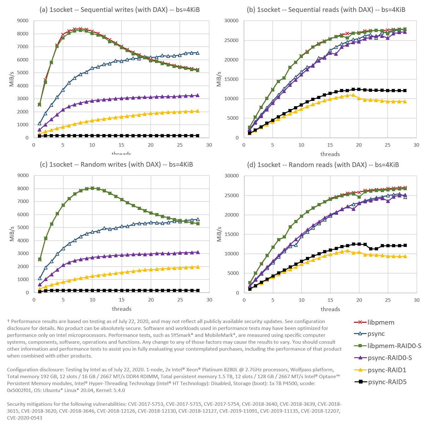
Figure 10. Using FIO, we compare software RAID 0, 1, and 5, against an interleaved configuration in a 1-socket environment for (a) sequential writes, (b) sequential reads, (c) random writes, and (d) random reads. The file system (XFS) is DAX enabled; I/O operation size (block size in FIO) is 4KiB.
Since NUMA is not an issue anymore, I will use the term “interleaved”—instead of “NUMA-aware”—to refer to the engines not running on RAID.
As you can see in Figure 10, the interleaved libpmem engine (dark red) is the winner again. This time, however, followed very closely by the libpmem engine running on RAID 0 (green), indicating that DAX is working as it should for RAID 0. Also close is the psync engine running on RAID 0 (purple) to the interleaved psync (dark blue), although this time only for reads.
Another interesting observation from this experiment is that reads for both RAID 1 and 5 perform better in one socket than in two. This tells us how impactful NUMA issues are when the routing of I/O operations is not done properly.
We can say that RAID 1 configurations are not recommended for one socket in light of these results. RAID 5 configurations are also not recommended, at least not as a general-purpose solution since the penalty imposed on writes is too high to justify them. Even on workloads dominated by reads, read performance falls short as well. However, this does not mean that RAID 5 may not be a good solution for some niche workloads, i.e., mostly reads in large chunks.
What about RAID 0? Even though RAID 0 seems to perform almost as good as interleaving when doing libpmem reads and writes, and psync reads, there is no strong incentive to use RAID 0 within one socket. There is no extra benefit, i.e., we don’t need RAID 0 to see the whole PMem capacity in the socket as a unified whole, since interleaving is giving us that already. Also, the Linux Logical Volume Manager can be used with one interleaved namespace too, giving us the flexibility of logical volumes without the need of a RAID configuration.
Fault Tolerance with Persistent Memory
It is clear by now that using software RAID 1 or 5 with Intel® Optane™ PMem modules is not ideal. Experimental data shows that performance degradations caused by software overheads are too high for them to make sense of this technology, leaving open the question of how to protect the data against module failure.
Realize that I started this article mentioning that RAID is a popular mechanism to improve performance or fault tolerance (or both). I never mentioned data protection. Data persistence does not necessarily equal data protection no matter the type of media used. In other words, RAID is not a substitute for backup; we should always implement a backup mechanism to protect our data.
There is still the question of fault tolerance. RAID 1 and 5 allows a system to continue operating when a module fails (albeit at a degraded performance). Without the redundancy provided by RAID 1 or 5, the system will stop servicing I/O requests and become inoperative. RAID 1 and 5, however, are not the only options. Another way to deal with this problem is to duplicate data remotely. By having copies of the data spread smartly among different servers, one can account for one server’s temporary shutdown (or more). In essence, remote replication “moves up” the responsibility of fault tolerance from the block layer in the OS (software RAID) to the application. Furthermore, remote replication has the added benefit that it also protects the system from failures in other hardware components, not only the I/O parts.
Node replication is how most modern NoSQL distributed databases (DBs), such as Apache Cassandra™, work. In Apache Cassandra, for example, one can configure a desired number of replicas. The amount of replication represents a trade-off between available space in the DB versus how many server failures we wish to tolerate simultaneously. When a write request arrives at a node (the coordinator) in the DB, the node will write the data to the replicas owning the row. How fast the coordinator responds depends on the consistency level specified by the client. For example, we can have a replication of three and a consistency level during a write of two. A consistency level of two means that at least two servers should acknowledge the write to be considered successful. The strongest possible protection is to always write with a consistency level that equals the configured replication.
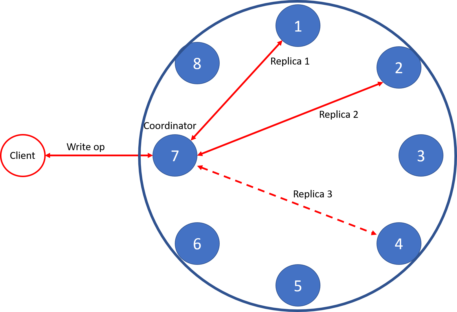
Figure 11: Write operation in Apache Cassandra™ with three replicas and consistency set to two.
As you can probably guess, Cassandra allows for the inconsistency of data between replicas, given that a user may want to write fast and not acknowledge that the write reached all replicas. In some situations, reads to different replicas can produce different versions of the data. That is why reads fetch data from all replicas to look for out-of-date data and synchronize accordingly. Nevertheless, users have different options during reads too. For example, they can read from just one replica. In that case, the user risks reading stale data, although that may be tolerable as long as the read finishes very fast.
To learn more about Cassandra, you can read its database internals documentation.
Summary
In this article, I explored software RAID possibilities for Intel® Optane™ persistent memory (PMem) modules. The RAID configurations tested were 0 (linear and striped), 1, and 5. Experiments conducted showed that RAID 0 configurations work well for 2-socket systems. RAID 0 configurations are desirable when developers want to see the system’s total PMem capacity as one big continuous chunk. RAID 0 configurations also perform well in one socket, but there is not a strong incentive to use them versus interleaving. Finally, experimental data showed that performance degradation caused by software overheads in RAID 1 and 5 is way too high to make sense with this technology, at least not until the code undergoes optimizations aimed for PMem devices. Instead of relying on RAID for fault tolerance, an alternative using remote replication was suggested at the end of the article with the Apache Cassandra DB example.
Appendix A: FIO Configuration
Note: The libpmem engine implementation in FIO up until commit 67719e1 is incorrect. The write path of the engine that uses non-temporal stores does not execute the SFENCE instruction at the end to ensure persistence is achieved after the write is completed. Versions 3.22 or lower of FIO still does not contain the needed code changes. For proper testing, either pull the latest primary branch, use a version higher than 3.22, or apply the changes from the following patch.
For brevity, only the FIO configuration file used for NUMA-aware workloads and two CPU sockets is shown. To run with one socket only, or for RAID, just delete the pnode1 section and adjust the cpus_allowed option accordingly. You may also want to change the number of files—or the total data size—depending on whether you run within one socket, with RAID over two sockets, or with RAID over one socket. Remember that RAID 1 has 1/2 the usable space of RAID 0. RAID 5 has (n-1)/n the usable space of RAID 0, where n is the number of namespaces used.
[global]
name=fio
rw=randrw
rwmixread=${RWMIX}
norandommap=1
invalidate=0
bs=${BLOCKSIZE}
numjobs=${THREADS}
time_based=1
clocksource=cpu
ramp_time=30
runtime=120
group_reporting=1
ioengine=${ENGINE}
iodepth=1
fdatasync=${FDATASYNC}
direct=${DIRECT}
sync=${SYNC}

[pnode0]
directory=${MOUNTPOINTSOCKET0}
size=630G
filename=file1.0.0:file1.0.1:file1.0.2:...:file1.0.62
file_service_type=random
nrfiles=63
cpus_allowed=0-27

[pnode1]
directory=${MOUNTPOINTSOCKET1}
size=630G
filename=file1.0.0:file1.0.1:file1.0.2:...:file1.0.62
file_service_type=random
nrfiles=63
cpus_allowed=28-55
Realize also that, for simplicity, not all files are listed for the parameter filename in the code snipped above. You must list every file there. The following parameters are used for the different experiments presented in this article:
| Color code | Figure # | # of sockets | RAID level | DAX available | $ENGINE | $FDATASYNC | $DIRECT | $SYNC |
|---|---|---|---|---|---|---|---|---|
|
|
4 | 2 | NUMA-aware | Yes | libpmem | 0 | 1 | 1 |
|
|
4 | 2 | NUMA-aware | Yes | psync | 1 | 0 | 0 |
| 4 | 2 | RAID 0 | Yes | libpmem | 0 | 1 | 1 | |
| 4 | 2 | RAID 0 | Yes | psync | 1 | 0 | 0 | |
| N/A | 7 | 2 | RAID 1 | No | psync | 1 | 1 | 0 |
| N/A | 8 | 2 | RAID 5 | No | psync | 1 | 1 | 0 |
|
|
9 | 1 | Interleaved | Yes | libpmem | 0 | 1 | 1 |
|
|
9 | 1 | Interleaved | Yes | psync | 1 | 0 | 0 |
|
|
9 | 1 | RAID 0 | Yes | libpmem | 0 | 1 | 1 |
|
|
9 | 1 | RAID 0 | Yes | psync | 1 | 0 | 0 |
|
|
9 | 1 | RAID 1 | No | psync | 1 | 1 | 0 |
|
|
9 | 1 | RAID 5 | No | psync | 1 | 1 | 0 |
Appendix B: XFS Configuration
Formatting and mounting are shown for one device only.
Without DAX:
# mkfs.xfs -f -i size=2048 -d su=2m,sw=1 /dev/path_to_the_device
...
# mount -t xfs -o noatime,nodiratime,nodiscard /dev/path_to_the_device /mountpoint
# xfs_io -c "extsize 2m" /mountpoint
With DAX:
# mkfs.xfs -f -i size=2048 -d su=2m,sw=1 -m reflink=0 /dev/path_to_the_device
...
# mount -t xfs -o noatime,nodiratime,nodiscard,dax /dev/path_to_the_device /mountpoint
# xfs_io -c "extsize 2m" /mountpoint
Appendix C: Volume Configuration
Creating Regions
Creation of interleaved regions:
# ipmctl create -f -goal
...
(reboot the system)
Creation of non-interleaved regions:
# ipmctl create -f -goal PersistentMemoryType=AppDirectNotInterleaved
...
(reboot the system)
Creating Namespaces
Namespace creation is shown for one region only (you can list available regions running ndctl list -RuN):
# ndctl create-namespace -m fsdax -M mem --region=region0
Configuring a Striped RAID 0
Configuring a striped RAID 0 volume (showing only for 2 namespaces):
# pvcreate -M2 --dataalignment 2m /dev/pmem0
# pvcreate -M2 --dataalignment 2m /dev/pmem1
# vgcreate --physicalextentsize 2m PmemVol /dev/pmem0 /dev/pmem1
# lvcreate -l 100%FREE -i 2 -I 2m -C y -n raid0s PmemVol
After running the above commands, the device /dev/PmemVol/raid0s is created.
Configuring a Linear RAID 0
Configuring a linear RAID 0 volume (showing only for 2 namespaces):
# pvcreate -M2 --dataalignment 2m /dev/pmem0
# pvcreate -M2 --dataalignment 2m /dev/pmem1
# vgcreate --physicalextentsize 2m PmemVol /dev/pmem0 /dev/pmem1
# lvcreate -l 100%FREE -n raid0l PmemVol
After running the above commands, the device /dev/PmemVol/raid0l is created.
Configuring RAID 1
Configuring a RAID 1 volume (showing only for 2 namespaces):
# pvcreate -M2 --dataalignment 2m /dev/pmem0
# pvcreate -M2 --dataalignment 2m /dev/pmem1
# vgcreate --physicalextentsize 2m PmemVol /dev/pmem0 /dev/pmem1
# lvcreate -l 100%FREE -m 1 -n raid1 PmemVol
After running the above commands, the device /dev/PmemVol/raid1 is created.
Configuring RAID 5
Configuring a RAID 5 volume (showing for 6 namespaces, i.e., one socket):
# pvcreate -M2 --dataalignment 2m /dev/pmem0
# pvcreate -M2 --dataalignment 2m /dev/pmem1
# pvcreate -M2 --dataalignment 2m /dev/pmem2
# pvcreate -M2 --dataalignment 2m /dev/pmem3
# pvcreate -M2 --dataalignment 2m /dev/pmem4
# pvcreate -M2 --dataalignment 2m /dev/pmem5
# vgcreate --physicalextentsize 2m PmemVol /dev/pmem0 /dev/pmem1 /dev/pmem2 /dev/pmem3 /dev/pmem4 /dev/pmem5
# lvcreate --type raid5 -i 5 -l 100%FREE -I 4k -n raid5 PmemVol
For a stripe size of 64 KiB, pass "-I 64k".
After running the above commands, the device /dev/PmemVol/raid5 is created.
Notices
† Performance results are based on testing as of July 22, 2020 and may not reflect all publicly available security updates. See configuration disclosure for details. No product can be absolutely secure. Software and workloads used in performance tests may have been optimized for performance only on Intel microprocessors. Performance tests, such as SYSmark* and MobileMark*, are measured using specific computer systems, components, software, operations and functions. Any change to any of those factors may cause the results to vary. You should consult other information and performance tests to assist you in fully evaluating your contemplated purchases, including the performance of that product when combined with other products.
Configuration disclosure: Testing by Intel as of July 22, 2020. 1-node, 2x Intel® Xeon® Platinum 8280L @ 2.7GHz processors, Wolfpass platform, Total memory 192 GB, 12 slots / 16 GB / 2667 MT/s DDR4 RDIMM, Total persistent memory 1.5 TB, 12 slots / 128 GB / 2667 MT/s Intel® Optane™ Persistent Memory modules, Intel® Hyper-Threading Technology (Intel® HT Technology): Disabled, Storage (boot): 1x TB P4500, ucode: 0x5002f01, OS: Ubuntu* Linux* 20.04, Kernel: 5.4.0
Security mitigations for the following vulnerabilities: CVE-2017-5753, CVE-2017-5715, CVE-2017-5754, CVE-2018-3640, CVE-2018-3639, CVE-2018-3615, CVE-2018-3620, CVE-2018-3646, CVE-2018-12126, CVE-2018-12130, CVE-2018-12127, CVE-2019-11091, CVE-2019-11135, CVE-2018-12207, CVE-2020-0543
Intel technologies’ features and benefits depend on system configuration and may require enabled hardware, software or service activation. Performance varies depending on system configuration. Check with your system manufacturer or retailer or learn more at intel.com.
No license (express or implied, by estoppel or otherwise) to any intellectual property rights is granted by this document.
Intel disclaims all express and implied warranties, including without limitation, the implied warranties of merchantability, fitness for a particular purpose, and non-infringement, as well as any warranty arising from a course of performance, course of dealing, or usage in trade.
This document contains information on products, services and/or processes in development. All information provided here is subject to change without notice. Contact your Intel representative to obtain the latest forecast, schedule, specifications and roadmaps.
The products and services described may contain defects or errors known as errata, which may cause deviations from published specifications. Current characterized errata are available on request.
Copies of documents which have an order number and are referenced in this document may be obtained by calling 1-800-548-4725 or by visiting www.intel.com/design/literature.htm.
"